
Ceramic laser perforating device

A laser drilling and laser cutting technology, applied in laser welding equipment, welding equipment, metal processing equipment, etc., can solve the problems of hole taper and roundness effects

Pending Publication Date: 2019-12-24
DONGGUAN INST OF OPTO ELECTRONICS PEKING UNIV
View PDF0 Cites 3 Cited by
  • Summary
  • Abstract
  • Description
  • Claims
  • Application Information

AI Technical Summary

Problems solved by technology

For lasers used for precision machining of ceramics, the diameter of the laser focal spot is generally ≤0.05mm. According to the thickness and size of the ceramic plate, through-hole drilling with different apertures can generally be achieved by controlling the defocus amount. For through-holes with a diameter of less than 0.15mm, Holes can be drilled by controlling the amount of defocus, but when the aperture is larger than 0.07mm, the larger the hole, the worse the quality of the hole, and the taper and roundness of the hole will be greatly affected

Method used


Image

  • Ceramic laser perforating device
  • Ceramic laser perforating device
  • Ceramic laser perforating device

Examples


Embodiment Construction

[0022] The present invention will be further described below in conjunction with the accompanying drawings.

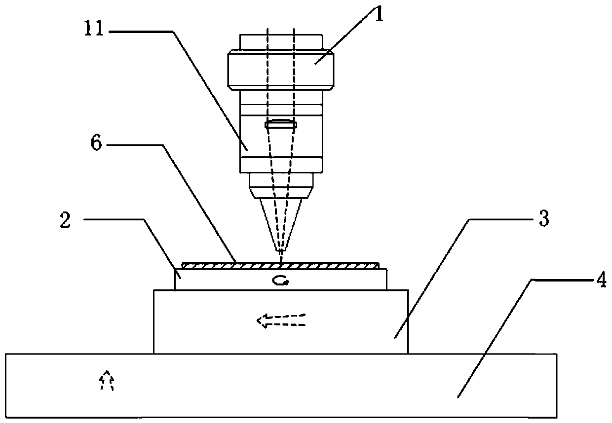
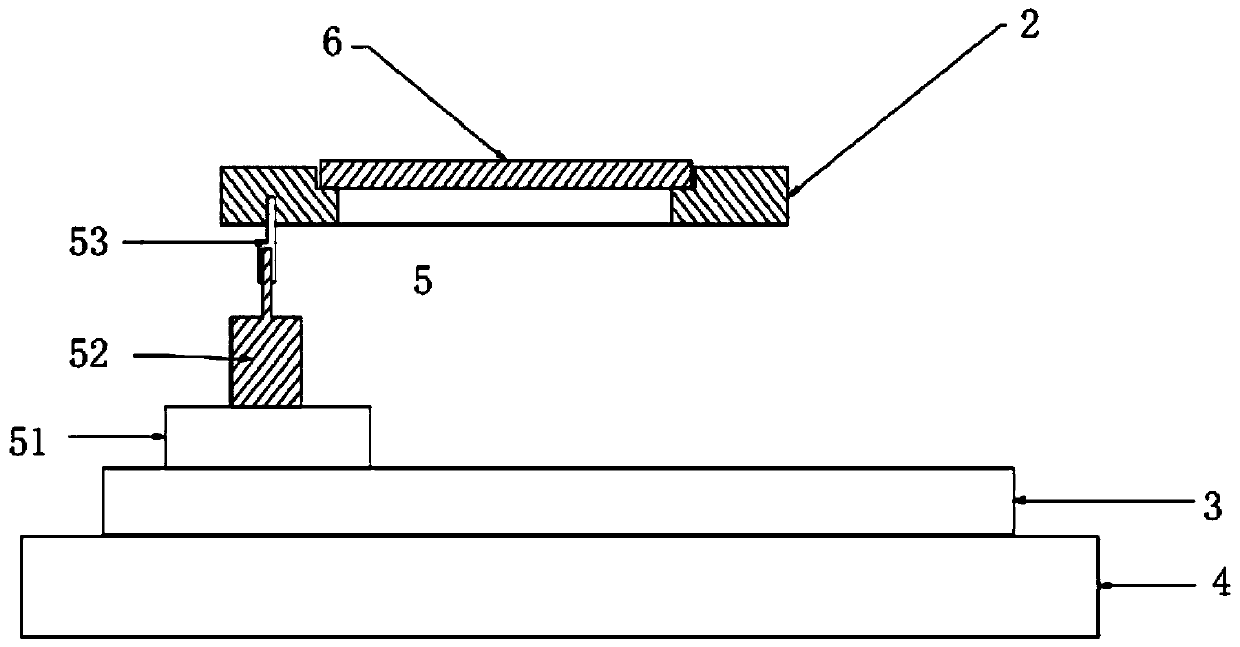
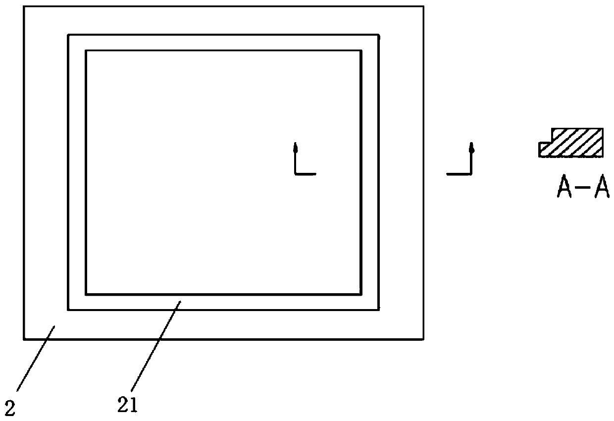
[0023] Such as Figure 1 ~ Figure 3 As shown, the laser drilling device of the present invention includes a laser cutting part 1 and a control device, and the laser cutting part 1 is connected to the control device, and also includes an X-axis motion mechanism 3, a Y-axis motion mechanism 4 and a rotary Vibration mechanism 2, the Y-axis movement mechanism 4 is installed on the workbench, the X-axis movement mechanism 3 is connected to the Y-axis movement mechanism 4, the gyratory vibration mechanism 2 is located below the laser cutting part 1, The gyratory vibration mechanism 2 is provided with an accommodating portion 21. When cutting ceramic materials, the ceramic material to be processed is placed in the accommodating portion 21, and the X-axis motion mechanism 3 and the Y-axis movement mechanism 3 are controlled by the control device. The shaft movement mechanism ...


PUM


Abstract

The invention relates to the technical field of laser processing equipment, in particular to a laser perforating device. The laser perforating device comprises a laser cutting portion, a control device and a workbench, and further comprises an X-axis movement mechanism, a Y-axis movement mechanism, a workbench and a rotary vibration mechanism. The rotary vibration mechanism is provided with an accommodating portion, when a ceramic material is cut, the ceramic material to be processed is placed in the accommodating portion, the control device controls the X-axis movement mechanism and the Y-axis movement mechanism to move, the coordinates of the center of the site of a hole perforated in the ceramic material to be processed are positioned, then the control device controls the rotary vibration mechanism to carry out rotary vibration to draw a circle, and the control device controls the laser cutting portion to emit a laser beam to complete perforation of the ceramic material to be process. By arrangement of the rotary vibration mechanism, for perforation of a through hole with the aperture greater than 0.07 mm, the perforation quality can be improved by a circle-drawing cutting mode,and the perforation efficiency is high.

Description

technical field [0001] The invention relates to laser processing equipment, in particular to a ceramic laser drilling device. Background technique [0002] Ceramic materials such as alumina and aluminum nitride have the advantages of high thermal conductivity, high insulation and high temperature resistance, and are widely used in the fields of electronics and semiconductors. However, ceramic materials have high hardness and brittleness, and their forming and processing are very difficult, especially the processing of micropores. Due to the high power density and good directionality of the laser, lasers are generally used to drill holes in ceramic plates. Laser ceramic drilling generally uses pulsed lasers or quasi-continuous lasers. The laser beam is focused on the laser axis through the optical system. placed on the workpiece, emitting a high energy density (10 5 -10 9 W / cm 2 ) laser beam melts and vaporizes the material, and an airflow coaxial with the beam is ejected...

Claims


Application Information

Patent Timeline
IPC IPC(8): B23K26/382B23K26/402B23K26/70
CPCB23K26/382B23K26/402B23K26/702
Inventor 王维昀郑小平王琦
Owner DONGGUAN INST OF OPTO ELECTRONICS PEKING UNIV
Learn More