Linkage adjustable precise piezoelectric stick-slip driving device and control method thereof
A driving device, piezoelectric technology, applied in the direction of piezoelectric effect/electrostrictive or magnetostrictive motors, electrical components, generators/motors, etc., can solve the problems of poor output response and low positioning accuracy, and achieve enhanced Response speed, high positioning accuracy, and fast output response
- Summary
- Abstract
- Description
- Claims
- Application Information
AI Technical Summary
Problems solved by technology
Method used
Image
Examples
specific Embodiment approach 1
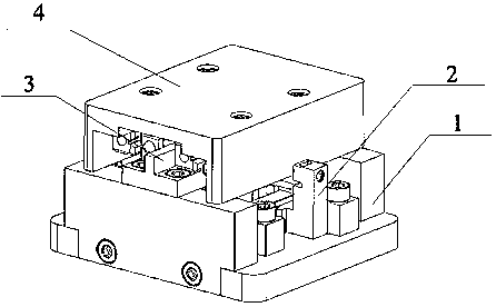
[0038] Specific implementation mode one: combine Figure 1~Figure 15 Describe this embodiment. This embodiment provides a specific implementation of a linkage adjustable precision piezoelectric stick-slip drive device. The specific implementation of the linkage and adjustable precision piezoelectric stick-slip drive device is expressed as follows:
[0039] The linkage adjustable precision piezoelectric stick-slip drive device is composed of a platform base unit 1, a drive unit 2, a guide rail unit 3 and an upper cover 4; wherein, the drive unit 2 is installed on the platform base unit 1 , the guide rail unit 3 is installed on the platform base unit 1 and located above the drive unit 2 , and the upper cover 4 is installed on the guide rail unit 3 and is in contact with the drive unit 2 .
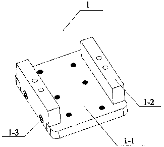
[0040] The platform base unit 1 includes a base bottom plate 1-1, a base side plate 1-2 and side plate fixing screws 1-3; the two base side plates 1-2 are fixed by the side plate fixing screw...
specific Embodiment approach 2
[0051] Specific implementation mode two: combination Figure 16 To illustrate this embodiment, this embodiment proposes a specific implementation of a control method for a linkage and adjustable precision piezoelectric stick-slip drive device. The control method for a linkage and controllable precision piezoelectric stick-slip drive device is expressed as follows:
[0052] In the control method, a double excitation electric signal group is adopted, the excitation electric signal A is a positive sawtooth wave electric signal, and the excitation electric signal B is a negative sawtooth electric signal. For Ⅰ2-6 and piezoelectric stack Ⅱ2-9:
[0053] t 1 ~t 2 Stage: The excitation electric signal A is a slow rising stage, which makes the piezoelectric stack Ⅰ2-6 slowly elongate; the excitation electric signal B is a slow falling stage, which makes the piezoelectric stack Ⅱ2-9 slowly shorten, forming hinge interlocking, and enhancing piezoelectric adhesion. Motion effect of sli...
PUM
 Abstract
Description
Claims
Application Information
 - R&D
- Intellectual Property
- Life Sciences
- Materials
- Tech Scout
- Unparalleled Data Quality
- Higher Quality Content
- 60% Fewer Hallucinations
Browse by: Latest US Patents, China's latest patents, Technical Efficacy Thesaurus, Application Domain, Technology Topic, Popular Technical Reports.
© 2025 PatSnap. All rights reserved.Legal|Privacy policy|Modern Slavery Act Transparency Statement|Sitemap|About US| Contact US: help@patsnap.com


