Power unit for electric vehicle

Active Publication Date: 2012-07-26
HONDA MOTOR CO LTD
View PDF6 Cites 36 Cited by
  • Summary
  • Abstract
  • Description
  • Claims
  • Application Information

AI Technical Summary

Benefits of technology

[0020]In these ways, when the load of the electric motor is large, a desired engine performance may be obtained by increasing the drive voltage of the electric motor. When the load of the electric motor is small, the drive voltage of the electric motor is prevented from becoming exceedingly large. Therefore, it is possible to enhance the driving efficiency of the inverter which drives and controls the electric motor. It is also possible to enhance the driving efficiency of the electric motor.
[0034]According to a power unit for an electric vehicle based on (6) above, the connection between the first power source and the second power source is switched between a connection in series and a connection in parallel by comparing the total loss of the electric motor and the power generator in the first connection condition and the total loss of the electric motor and the power generator in the second connection condition. As a result, the electric vehicle mounted with the power unit may be operated efficiently.

Problems solved by technology

Therefore, during an AER (All Electric Range) travel, when the vehicle is run only with electric power supplied by the battery without using power from an internal combustion, the voltage adjustment cannot be performed.
Therefore, there is a problem in that the connection of a plurality of battery modules cannot be switched.
Further, when the connection of a plurality of battery modules is switched, there is a problem in that a travel control is suspended because, since the switch is released, there is a shut-off in the electric power supply from the battery to the inverter driving and controlling each motor generator, and because there is no electric power buffer device other than the battery which can supply electric power to the inverter.
However, it is not easy to perform such a switching operation.
Hence, when the switch is fastened once again after a switching of the connection of the plurality of battery modules is completed, there is a risk that an exceedingly large amount of electric current will run through suddenly.

Method used


Image

  • Power unit for electric vehicle
  • Power unit for electric vehicle
  • Power unit for electric vehicle

Examples


Embodiment Construction

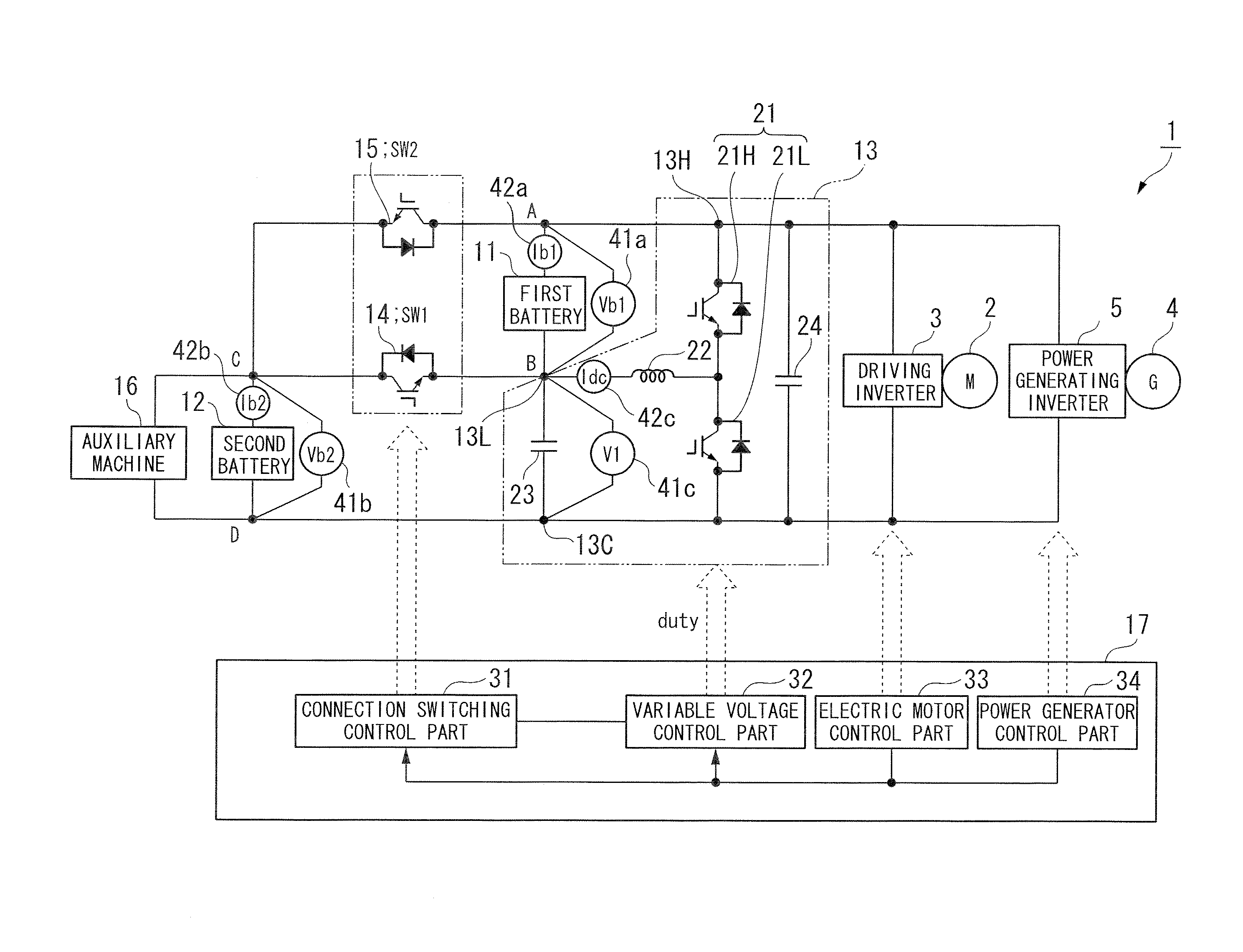
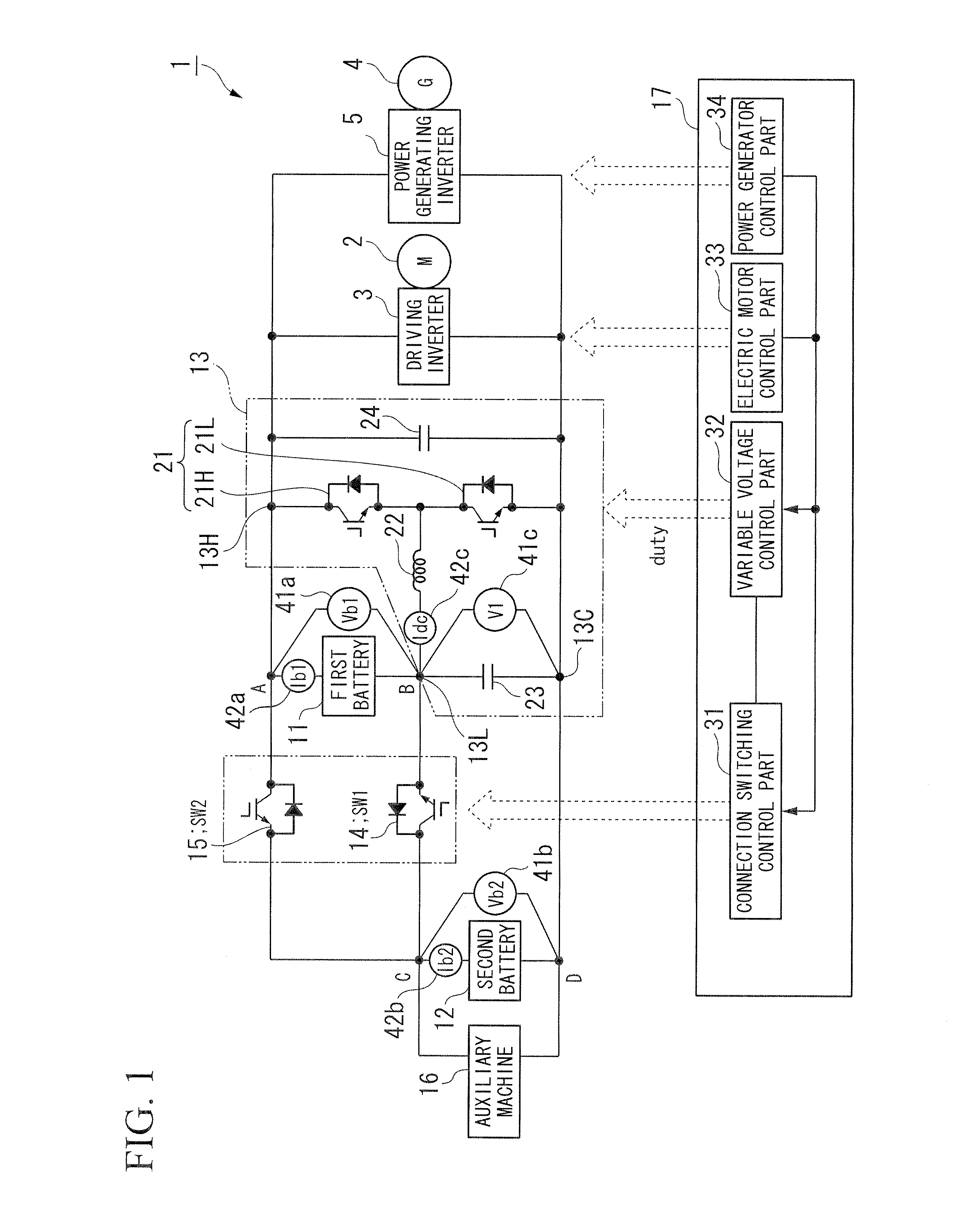
[0068]Hereunder, a power unit for an electric vehicle according to an embodiment of the present invention is described with reference to the attached diagrams.

[0069]As shown in FIG. 1, for example, the power unit 1 for the electric vehicle according to the above embodiment comprises a power source supplying electric power to a driving inverter 3 for driving and controlling a electric motor (M) 2 generating a cruise driving force of the electric vehicle.

[0070]Incidentally, the driving inverter 3 is configured so that a power generating inverter 5 (an inverter for generating power), which controls a power generation of a power generator (G) 4, is connected in parallel with respect to the power unit 1 for the electric vehicle. It is possible to supply electric power from the power generating inverter 5 to the driving inverter 3.

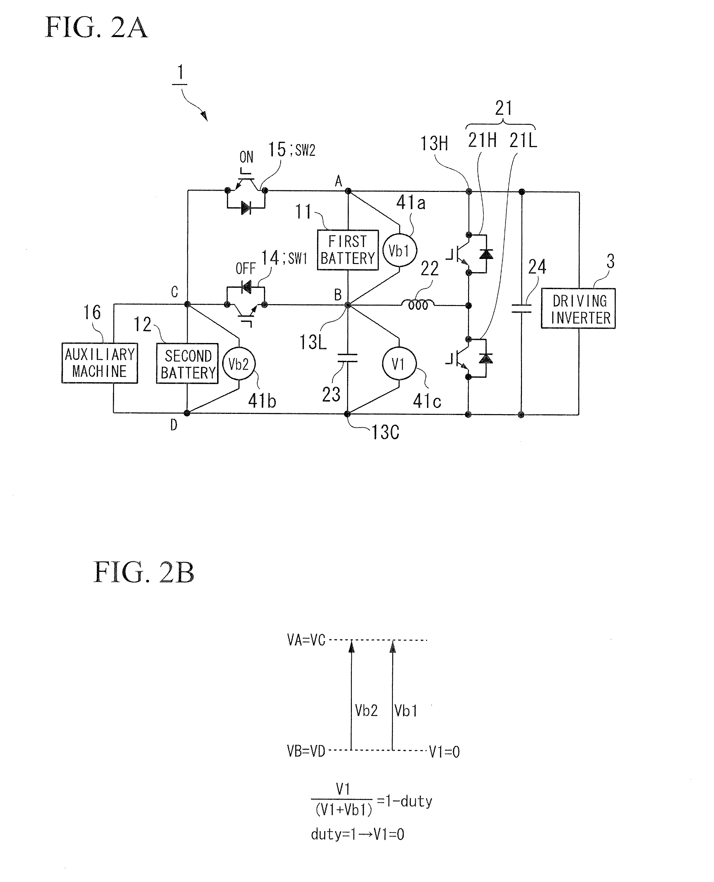
[0071]The power unit 1 for the electric vehicle comprises a first node A, a second node B, a third node C, a fourth node D, a first battery 11, a second battery...


PUM


Abstract

A power unit for an electric vehicle includes: a first power source connected between a first node and a second node; a first switch connected between the second node and a third node; a second power source connected between the third node and a fourth node; a second switch connected between the first node and the third node; and a DC-DC converter connected to the second node, wherein the DC-DC converter changes an electric potential of the second node by making the second node connectable to the fourth node or the third node, and an output electric power obtained from between the first node and the fourth node is supplied to an electric motor.

Description

TECHNICAL FIELD[0001]The present invention relates to a power unit for an electric vehicle.[0002]Priority is claimed on Japanese Patent Application No. 2011-010584, filed Jan. 21, 2011, the content of which is incorporated herein by reference.BACKGROUND ART[0003]Conventionally, a hybrid vehicle is known which includes a first motor generator connected to an internal combustion, a second motor generator connected to a drive wheel, and a voltage-controlled battery connected to an inverter via a switch, for example. The inverter drives and controls each motor generator. Each motor generator performs a voltage adjustment when a connection of a plurality of battery modules included in the voltage-controlled battery is switched between a connection in parallel and a connection in series. In this way, the switch is released. (See, for example, Japanese Patent No. 4353093.)DISCLOSURE OF INVENTION[0004]Incidentally, according to the hybrid vehicle based on the conventional technology describ...

Claims


Application Information

Patent Timeline
IPC IPC(8): H02P23/00H02J7/00
CPCB60L11/1868H02M1/10Y02T10/7066Y02T10/7005H02M3/158B60L58/20Y02T10/70
Inventor SONE, TOSHIHIRO
Owner HONDA MOTOR CO LTD
Why Eureka
Try Eureka