Carbon fiber acoustic baffle applied to underwater detection equipment

An underwater detection equipment and carbon fiber technology, applied in the field of vibration reduction and noise reduction, can solve the problems of interfering with the normal operation of underwater acoustic detection equipment, insufficient strength of low-density foam materials, and heavy sound baffle plate, and improve the detection performance of the equipment. , excellent sound insulation performance, reducing the effect of vibration transmission

Pending Publication Date: 2019-12-20
HARBIN ENG UNIV +1
View PDF0 Cites 4 Cited by
  • Summary
  • Abstract
  • Description
  • Claims
  • Application Information

AI Technical Summary

Problems solved by technology

[0002] The bulbous bow of modern large and medium-sized ships is mostly equipped with underwater detection equipment, and its performance is affected by the acoustic environment in the bulbous bow dome. The vibration and noise of the equipment interfere with the normal operation of the underwater acoustic detection equipment. At present, the acoustic baffle is gradually applied to the bulbous bow dome as a noise reduction structure to reduce the water load generated by the propeller and mechanical equipment from the stern. Noise, the structural design of sound baffles mainly focuses on metal and low-density foam materials. Metal sound baffles have the problems of heavy weight and inconvenient installation in small spaces. Low-density foam materials also have insufficient strength and require other structures Auxiliary supports and other defects, therefore, the present invention proposes a carbon fiber acoustic baffle for underwater detection equipment to solve the problems in the prior art

Method used


Image

  • Carbon fiber acoustic baffle applied to underwater detection equipment
  • Carbon fiber acoustic baffle applied to underwater detection equipment
  • Carbon fiber acoustic baffle applied to underwater detection equipment

Examples


Embodiment Construction

[0018] In order to deepen the understanding of the present invention, the present invention will be further described below in conjunction with the examples, which are only used to explain the present invention, and do not constitute a limitation to the protection scope of the present invention.

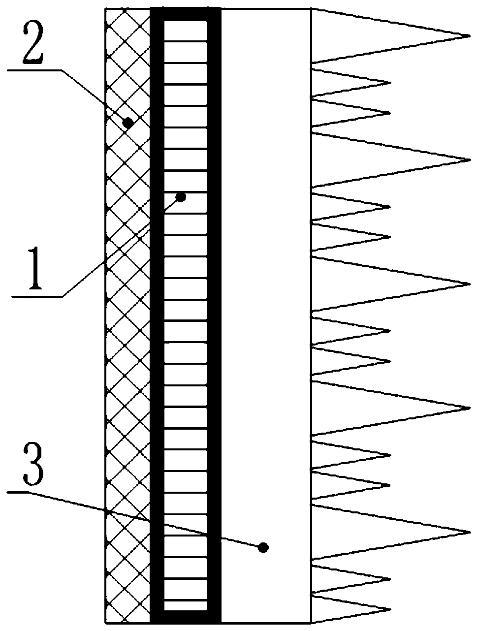
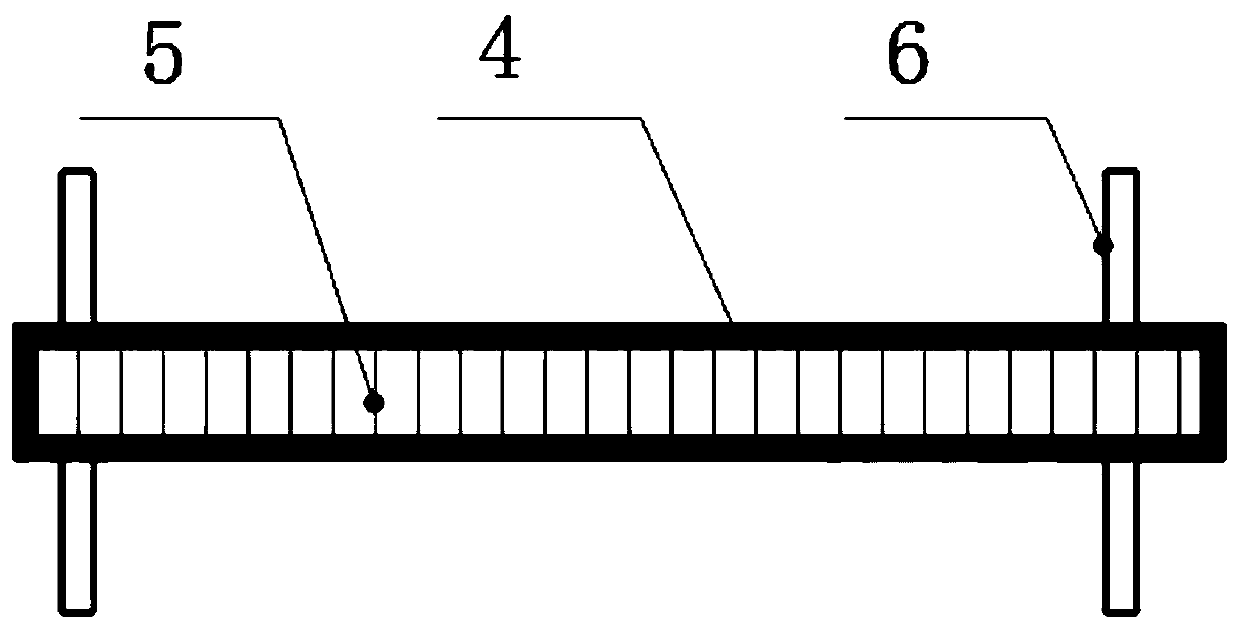
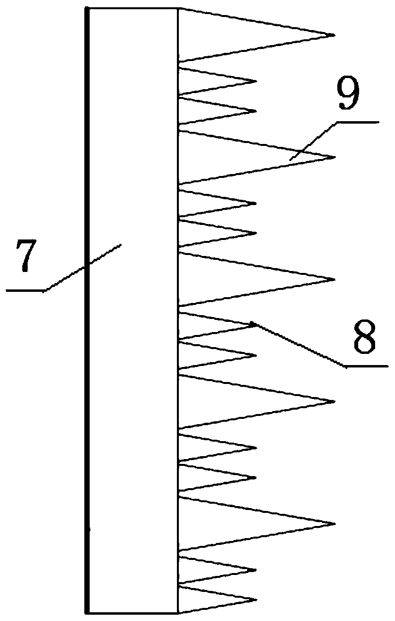
[0019] according to figure 1 , 2 , 3, this embodiment provides a carbon fiber acoustic baffle for underwater detection equipment, including a baffle main body 1, a damping layer 2 and a sound-absorbing layer 3, one side of the baffle main body 1 is tightly bonded A damping layer 2 is combined, and the other side of the baffle main body 1 is tightly bonded with a sound-absorbing layer 3. The baffle main body 1 adopts a structure in which an outer shell 4 wraps a carbon fiber honeycomb core material 5, and the carbon fiber honeycomb core material 5 and The outer casing 4 is composed of carbon fiber reinforced resin, the outer casing 4 and the carbon fiber honeycomb core material 5 are...


PUM

PropertyMeasurementUnit
diameteraaaaaaaaaa
thicknessaaaaaaaaaa
thicknessaaaaaaaaaa

Abstract

The invention discloses a carbon fiber acoustic baffle applied to underwater detection equipment. The carbon fiber acoustic baffle applied to the underwater detection equipment includes a baffle body,a damping layer and a sound absorbing layer; the damping layer is closely adhered to one side of the baffle body, and the sound absorbing layer is closely adhered to the other side of the baffle body; the baffle body 1 adopts a structural form in which a shell wraps a carbon fiber honeycomb core material, and the carbon fiber honeycomb core material and the shell are both a carbon fiber reinforced resin composite structure; the shell and the carbon fiber honeycomb core material are bonded by resin; and the carbon fiber honeycomb core material forms cavities with the inside of the shell. According to the invention, the structural form in which the shell wraps the carbon fiber honeycomb core material is adopted; the carbon fiber honeycomb core material and the shell form a large number of independent and closed cavities as the sound insulation structure; and the propeller noise, mechanical noise and hull vibration sound radiation from the stern are blocked by using the impedance mismatch effect; therefore, the impact of such noise on the underwater detection equipment is reduced, and the detection performance of the equipment is improved.

Description

technical field [0001] The invention relates to the technical field of vibration reduction and noise reduction, in particular to a carbon fiber acoustic baffle used for underwater detection equipment. Background technique [0002] The bulbous bow of modern large and medium-sized ships is mostly equipped with underwater detection equipment, and its performance is affected by the acoustic environment in the bulbous bow dome. The vibration and noise of the equipment interfere with the normal operation of the underwater acoustic detection equipment. At present, the acoustic baffle is gradually applied to the bulbous bow dome as a noise reduction structure to reduce the water load generated by the propeller and mechanical equipment from the stern. Noise, the structural design of sound baffles mainly focuses on metal and low-density foam materials. Metal sound baffles have the problems of heavy weight and inconvenient installation in small spaces. Low-density foam materials also h...

Claims


Application Information

Patent Timeline
Patent Type & Authority Applications(China)
IPC IPC(8): G10K11/162G10K11/168G10K11/172
CPCG10K11/162G10K11/168G10K11/172
Inventor 叶天贵靳国永林壮董丹杨东凯张艳涛李平刘志刚
Owner HARBIN ENG UNIV
Why Eureka
Try Eureka