Doppler velocimeter for lead fish

A Doppler flow meter and lead fish technology, applied in the field of flow meters, can solve the problems of increasing labor costs, measurement interruption, and more garbage and debris, and achieve the effects of robust and durable probes, reduced labor costs, and accurate measurement data.

Pending Publication Date: 2019-12-20
南宁强国科技有限公司
View PDF12 Cites 1 Cited by
  • Summary
  • Abstract
  • Description
  • Claims
  • Application Information

AI Technical Summary

Problems solved by technology

In the prior art, relying on this method to measure hydrological velocity and flow has encountered several similar problems: first, due to the eutrophication of the environment, the aquatic plants in the river channel have multiplied in large numbers, causing the traditional current meter (rotary propeller, rotary cup) to often It is entangled, resulting in measurement interruption or measurement failure or measurement data error; second, there are a lot of garbage in the river, which can easily cause damage to the traditional flow meter (rotary propeller, rotary cup); third, it needs to be restarted after a certain period of time. Calibrate the K, C, and N values ​​of the flow meter, and the flow meter cannot be placed outdoors for a long time. Long-term wind and rotation will quickly cause the K, C, and N values ​​​​to shift or be scrapped
Fourth, the measurement range of the traditional current meter is small, and there are low-speed current meter and high-speed current meter respectively. If the river flow rate range is large, two current meters are required.
Fifth, because the traditional current meter cannot be placed outdoors for a long time, it is necessary to manually install the current meter on site every time the flow is measured, and each hydrological station needs to arrange personnel to be on duty, which increases labor costs and is troublesome to realize remote flow measurement
However, the existing tow-type Doppler current meter in the prior art cannot enter the water to measure the flow, and the general flow measurement range is 0.3-5m / s

Method used


Image

  • Doppler velocimeter for lead fish
  • Doppler velocimeter for lead fish
  • Doppler velocimeter for lead fish

Examples


Embodiment Construction

[0032] The present invention will be described in detail below in conjunction with the accompanying drawings and embodiments.

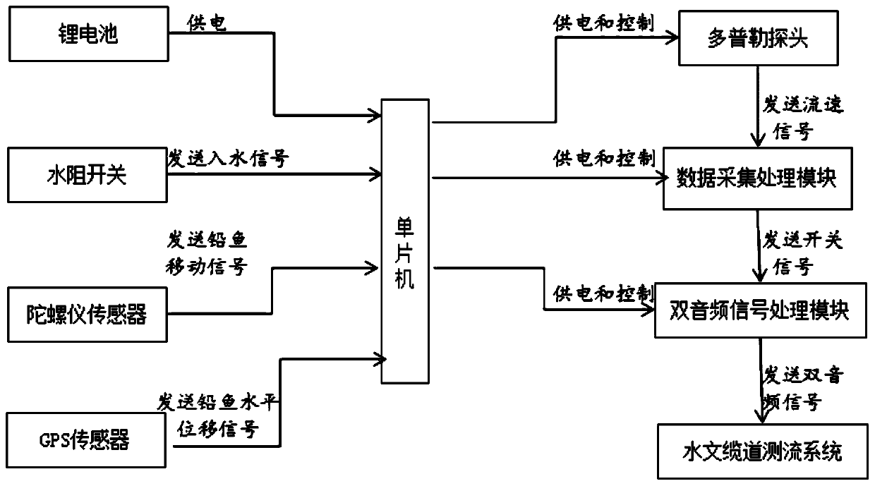
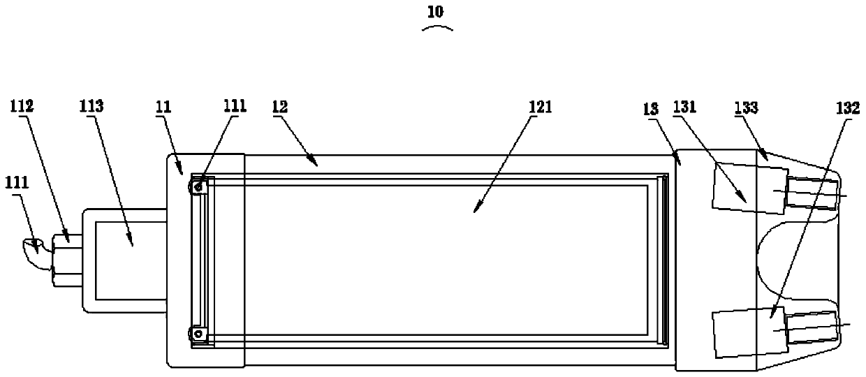
[0033] In one embodiment of the present invention, refer to Figure 1 to Figure 5, providing a Doppler current meter for lead fish, comprising a signal acquisition module (not shown), a signal processing module 20, a lithium battery 40 and a single-chip microcomputer, the signal acquisition module comprising a Doppler probe 10 and a lead fish signal acquisition module, The Doppler probe 10 is arranged on the front end of the lead fish, and the signal processing module is fixed on the rear end or the middle part of the lead fish; it is preferably fixed on the middle part of the lead fish, which can reduce the number of wires connected between the Doppler probe 10 and the signal processing module. The length of the cable can avoid problems caused by the cable being too long during the operation; at the same time, it is fixed in the middle of the lead fi...


PUM


Abstract

The invention discloses a Doppler velocimeter for lead fish. The Doppler velocimeter comprises a signal acquisition module, a signal processing module, a lithium battery and a single-chip microcomputer, wherein the signal acquisition module comprises a Doppler probe and a lead fish signal acquisition module, the Doppler probe is arranged at the front end of the lead fish, and the signal processingmodule is fixed at the back end or in the middle of the lead fish; the single-chip microcomputer acquires a lead fish signal from the lead fish signal acquisition module and transmits the lead fish signal to the signal processing module; the signal processing module is connected with the Doppler probe and receives a flow velocity signal sent by the Doppler probe; and the signal processing moduleprocesses the received lead fish signal and flow velocity signal and then transmits the signals to a hydrologic cableway flow measuring system under the control of the single-chip microcomputer. The Doppler velocimeter detects the flow velocity with the Doppler probe by an ultrasonic technology, and is wide in measurement range and high in measured data accuracy.

Description

technical field [0001] The invention relates to the field of flow meters for hydrological testing, in particular to a Doppler flow meter for lead fish. Background technique [0002] At present, the country is intensifying efforts to develop hydrology, requiring technological innovation. However, in the prior art, a propeller current meter, a rotary cup current meter, and a towed Doppler current meter are mainly used for hydrological testing. Both the propeller flowmeter and the rotary cup flowmeter are rotor-type flowmeters, and the working principle is basically the same. It uses the power of water flow to drive the rotor to rotate, and then calculates the flow velocity through K, C, and N. The flow velocity calculation formula: V=KN+C; In the formula: V-flow velocity (m / s); N-number of dual audio signals; K-constant; C-instrument calibration coefficient. In the prior art, relying on this method to measure hydrological flow velocity and flow has encountered several simila...

Claims


Application Information

Patent Timeline
Patent Type & Authority Applications(China)
IPC IPC(8): G01P5/24G01S15/58G01P1/02G01S7/521H02J7/35
CPCG01P5/241G01S15/58G01P1/026G01S7/521H02J7/35
Inventor 张立王飞周德政周建刚雷瑀韦治高雷运区
Owner 南宁强国科技有限公司
Why Eureka
Try Eureka