
Mass spectrometer

a mass spectrometer and mass spectrometer technology, applied in the field of mass spectrometers, can solve the problems of selectivity (or mass resolution), difficult to generate a wide range rf voltage without and difficult to generate rf voltages with a specific frequency or a specific frequency band. achieve the effect of enhancing the reliability and accuracy of mass analysis, high reliability and high accuracy

Active Publication Date: 2007-05-01
SHIMADZU CORP
View PDF9 Cites 26 Cited by
  • Summary
  • Abstract
  • Description
  • Claims
  • Application Information

AI Technical Summary

Benefits of technology

This approach enables high-resolution mass analysis and reliable identification of sample components by selectively storing and analyzing ions with precise mass to charge ratios, reducing impurities and improving structural analysis accuracy.

Problems solved by technology

However, it is difficult to generate a wide range RF voltage devoid of a specific frequency or a specific frequency band.
It is also difficult to generate an RF voltage having a specific frequency or a specific frequency band.
Therefore, the mass selectivity (or mass resolution) of ions of the above ion trap is not satisfactory, and it is difficult to adequately eliminate ions having very close (0.01 amu, for example) mass to charge ratio to object ions.

Method used


Image

  • Mass spectrometer
  • Mass spectrometer
  • Mass spectrometer

Examples


Embodiment Construction

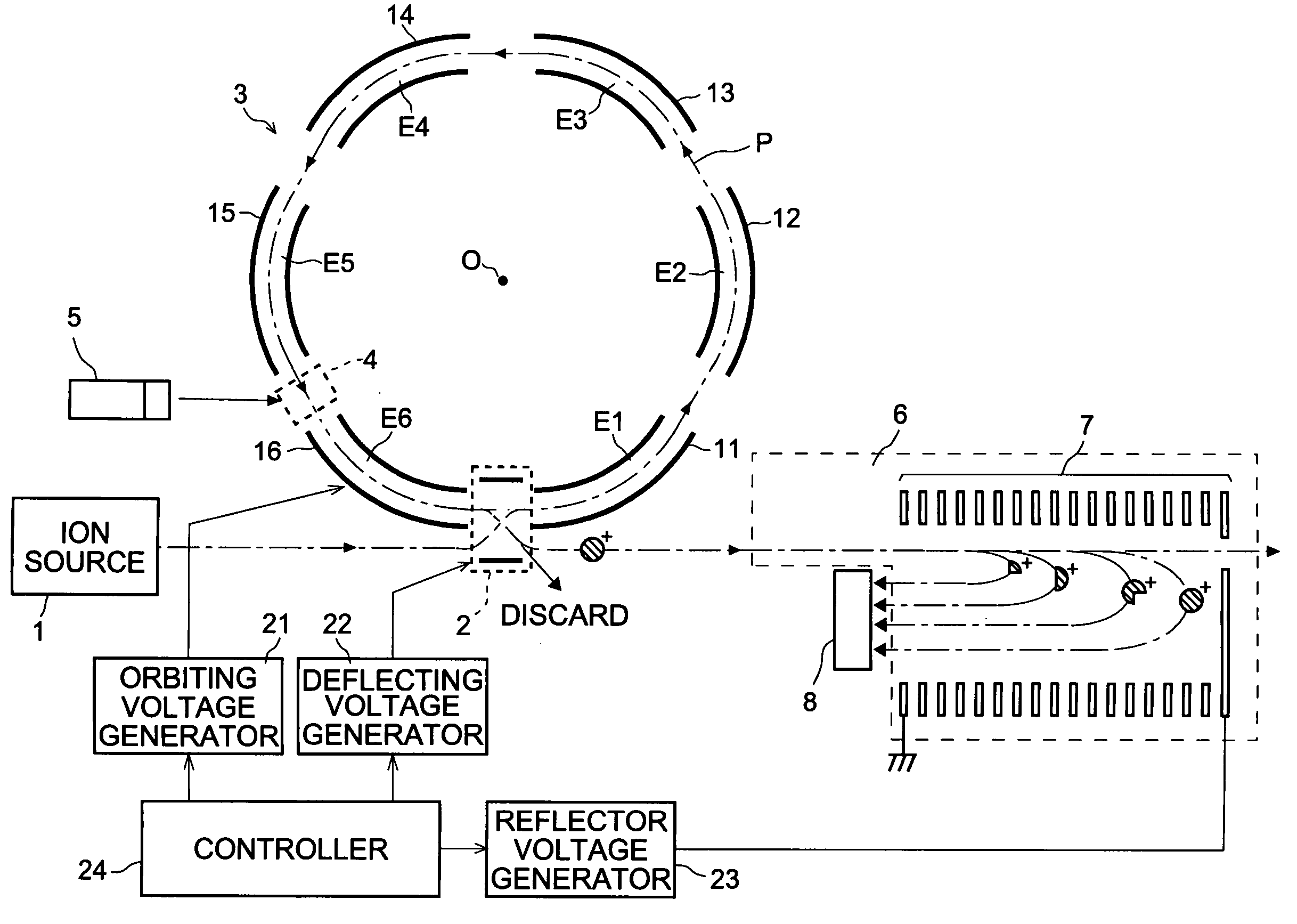
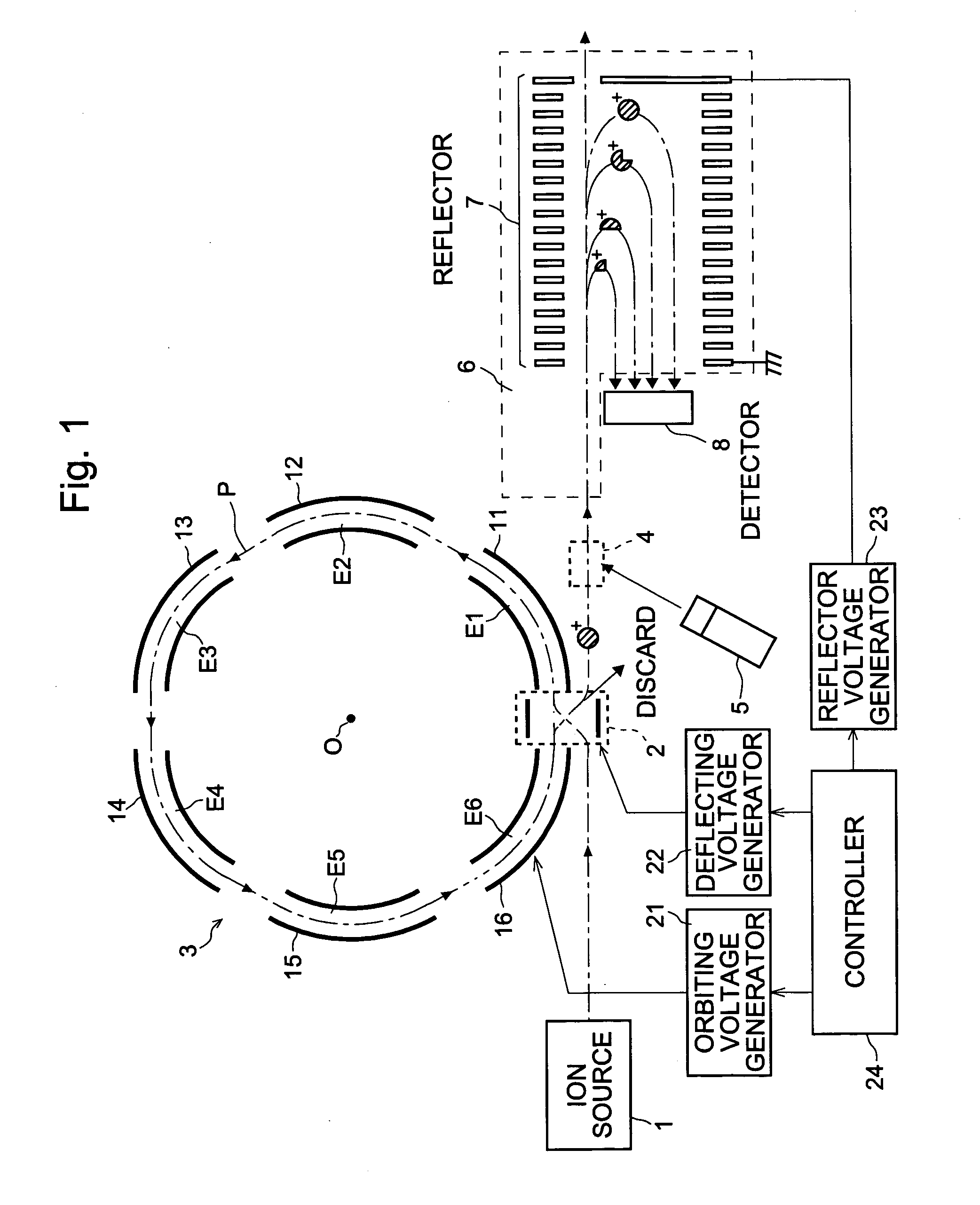
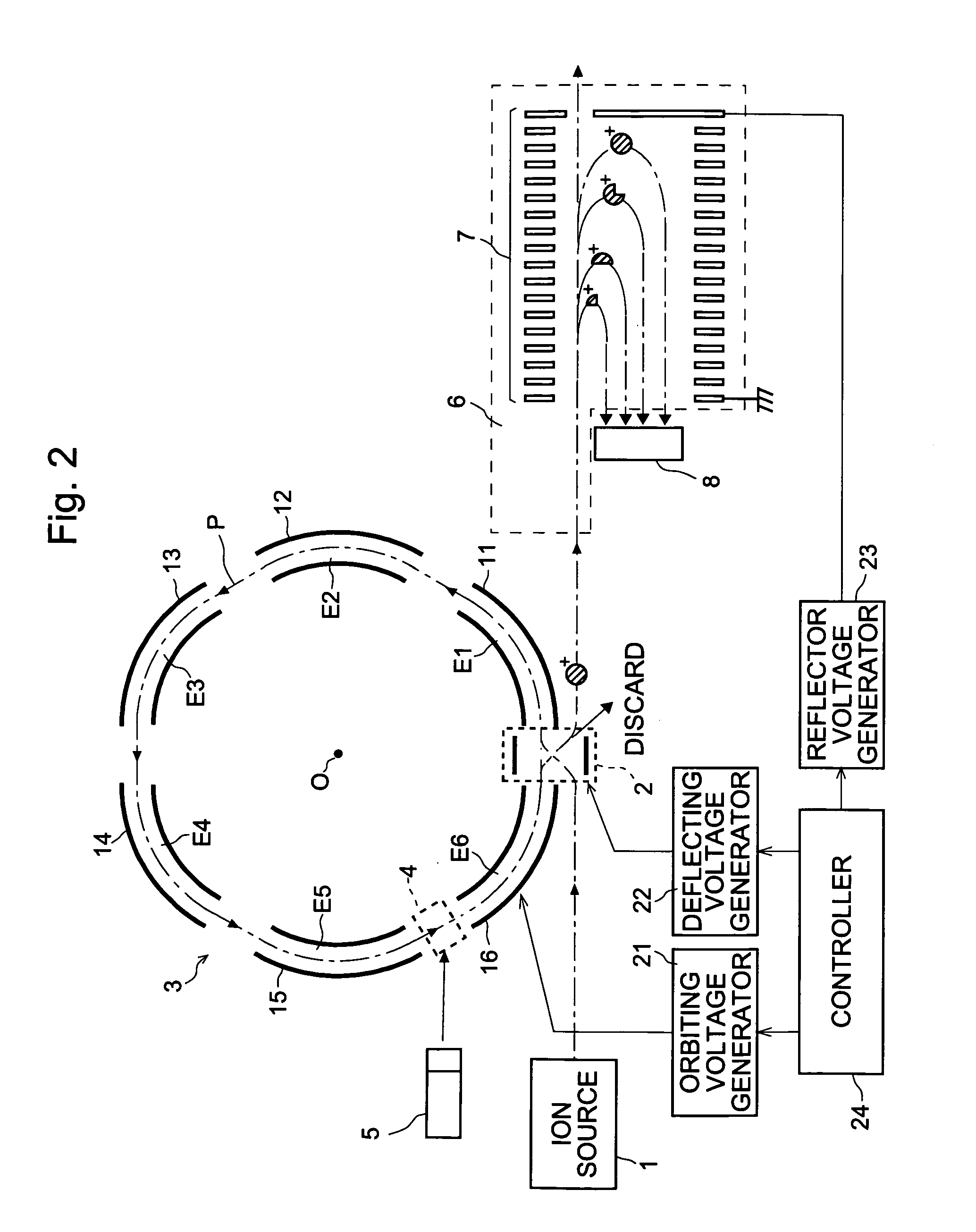
[0024]A mass spectrometer embodying the present invention is described referring to FIG. 1. In a vacuum chamber (not shown) of the mass spectrometer, an ion source 1, a first flight space 3, a second flight space 6, and an ion detector 8 are provided with other ordinary devices. In the second flight space 6, a reflector 7 is provided.

[0025]In the ion source 1, molecules of a sample are ionized with an appropriate conventional method. When the mass spectrometer of the present embodiment is used as a detector of a gas chromatograph (GC), for example, the ion source 1 uses the electron impact ionization (EI) method, or the chemical ionization (CI) method. When it is used as a detector of a liquid mass chromatograph (LC), the ion source 1 uses the atmospheric pressure chemical ionization (APCI) method or the electro-spray ionization (ESI) method. When high polymer compounds such as protein are to be analyzed, the matrix-assisted laser desorption ionization (MALDI) method is appropriate....


PUM

PropertyMeasurementUnit
mass to charge ratiosaaaaaaaaaa
mass to charge ratioaaaaaaaaaa
mass spectrometeraaaaaaaaaa

Abstract

In the mass spectrometer of the present invention, a flight space is provided before the mass analyzer, and the flight space includes a loop orbit on which ions fly repeatedly. While ions fly on the loop orbit repeatedly, ion selecting electrodes placed on the loop orbit selects object ions having a specific mass to charge ratio in such a manner that, for a limited time period when the object ions are flying through the ion selecting electrodes, an appropriate voltage is applied to the ion selecting electrodes to make them continue to fly on the loop orbit, but otherwise to make or let other ions deflect from the loop orbit. If ions having various mass to charge ratios are introduced in the loop orbit almost at the same time, the object ions having the same mass to charge ratio continue to fly on the loop orbit in a band, but ions having mass to charge ratios different from that are separated from the object ions while flying on the loop orbit repeatedly. Even if the difference in the mass to charge ratio is small, the separation becomes large when the number of turns of the flight becomes large. After such a separation is adequately achieved, the ion selecting electrodes can select the object ions with high selectivity, or at high mass resolution. By adding dissociating means, fragment ions originated only from the selected object ions can be analyzed, which enables the identification and structural analysis of the sample at high accuracy.

Description

[0001]The present invention relates to a mass spectrometer, especially to one that selects and stores ions of a specific mass to charge ratio or ratios among ions having various mass to charge ratios.BACKGROUND OF THE INVENTION[0002]The international publication WO99 / 39368 discloses a mass spectrometer including the elements of: an ion trap device as an ion source; a flight space for letting ions from the ion source fly straight; a reflector for reflecting back the ions flying the flight space using an electric field; and a detector for detecting ions that have flown the flight space. The ion trap device is composed of a ring electrode and a pair of end cap electrodes placed opposite to each other with the ring electrode therebetween. Applying appropriate voltages to the electrodes, a three-dimensional quadrupole electric field is generated in the space (ion trap space) surrounded by the electrodes, where ions are stored, or ions of a specific mass to charge ratio or ratios are sele...

Claims


Application Information

Patent Timeline
Patent Type & Authority Patents(United States)
IPC IPC(8): B01D59/44H01J49/00G01N27/62H01J49/06H01J49/16H01J49/26H01J49/40
CPCH01J49/408
Inventor YAMAGUCHI, SHINICHIISHIHARA, MORIOTOYODA, MICHISATOOKUMURA, DAISUKE
Owner SHIMADZU CORP
Learn More