Energy storage device with charging and discharging functions, wireless charging system and electric vehicle

An energy storage device, charging and discharging technology, applied in the direction of electric vehicles, electric vehicle charging technology, circuit devices, etc., can solve the problems of not considering the integration of other vehicle circuit components, complex heat dissipation system, large volume and weight of circuit components, etc.

Pending Publication Date: 2019-12-20
HUAWEI DIGITAL POWER TECH CO LTD
View PDF5 Cites 7 Cited by
  • Summary
  • Abstract
  • Description
  • Claims
  • Application Information

AI Technical Summary

Problems solved by technology

[0003] At present, the energy storage device of an electric vehicle mainly includes a battery module, a cooling plate and a battery management system BMS, and the integration of other on-board circuit components is not considered, and some circuit components are relatively large in size and weight, occupying a large space at the bottom of the vehicle
In addition, the problem of heat dissipation is also serious during long-term continuous work. It is necessary to design heat dissipation for different circuit components, and the heat dissipation system is more complicated.

Method used


Image

  • Energy storage device with charging and discharging functions, wireless charging system and electric vehicle
  • Energy storage device with charging and discharging functions, wireless charging system and electric vehicle
  • Energy storage device with charging and discharging functions, wireless charging system and electric vehicle

Examples


Embodiment Construction

[0034] The purpose of the present application is to overcome the above-mentioned shortcomings of the prior art, realize the highly integrated, miniaturized, and lightweight rechargeable and dischargeable energy storage devices, and ensure the charging efficiency and safety of wireless charging.

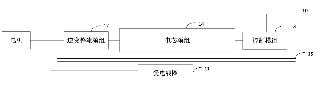
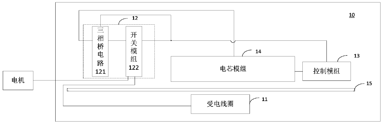
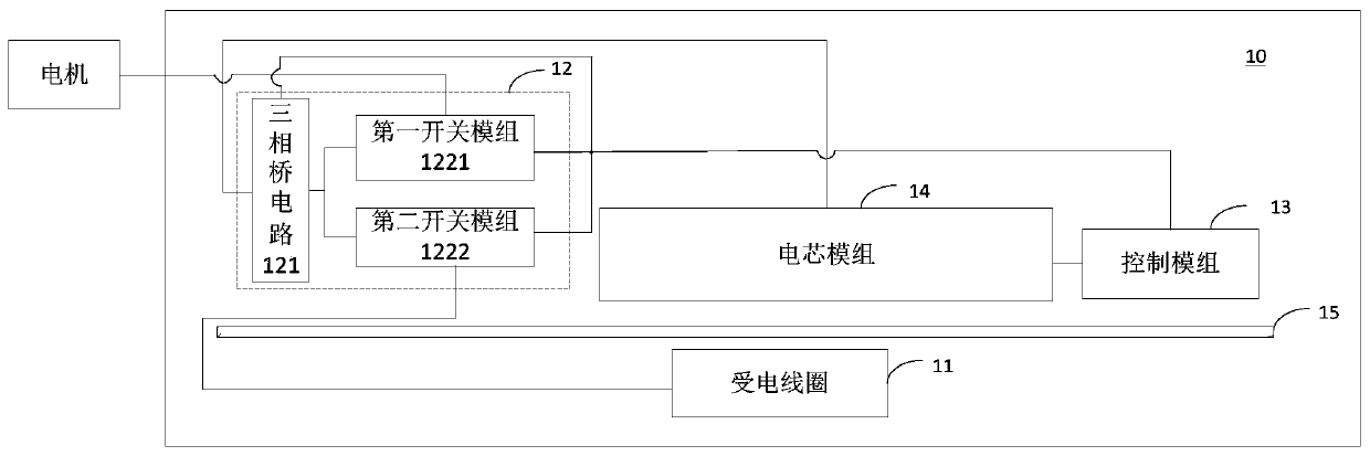
[0035] In order to achieve the above purpose, an embodiment of the present application provides a rechargeable and dischargeable energy storage device including a power receiving coil, an inverter rectifier module, a control module and a battery module. The inverter rectifier module is connected to the power receiving coil, The control module is connected to the battery module, and the control module is also connected to the battery module. The inverter rectifier module is controlled by the control module to realize the charging or discharging function, and the control module is also used to monitor the working status of the battery module to ensure that the battery module works in a n...


PUM


Abstract

The invention provides an energy storage device with charging and discharging functions, a wireless charging system and an electric vehicle. The energy storage device with the charging and dischargingfunctions comprises an electricity receiving coil, an inverting and rectifying module, a control module, a cell module and a cooling plate. The inverting and rectifying module is connected with the electricity receiving coil, the control module and the cell module. The cell module and the control module are connected. The electricity receiving coil is arranged on the lower side of the cooling plate. The electricity receiving coil is used for generating alternating current when receiving an alternating magnetic field generated by a transmitting coil located on the ground. The control module isused for controlling the inverting and rectifying module to convert alternating current output by the electricity receiving coil into direct current and output the direct current to the cell module and also used for controlling the inverting and rectifying module to convert direct current output by the cell module into alternating current to drive a motor to work. The energy storage device with the charging and discharging functions integrates an inverter and a rectifier in the electrical principle, so that the number of assemblies of the energy storage device is reduced, and the manufacturing cost is lowered. The control module in the energy storage device integrates three controller functions, so that the overall control efficiency of the energy storage device is improved.

Description

technical field [0001] The present application relates to the field of electric vehicles, in particular to a chargeable and dischargeable energy storage device, a wireless charging system and an electric vehicle. Background technique [0002] As a representative of new energy vehicles, electric vehicles have the advantages of environmental protection, zero emission, and convenient use, and the market demand is increasing year by year. Electric vehicles rely on the on-board battery pack to provide power, and the on-board battery pack needs to be charged in time to ensure sufficient power. At present, the main charging method is wired charging such as charging piles. This charging method has safety risks such as plugging in and sparking, leakage, etc., and is not easy to maintain. As an innovative technology direction, the wireless charging technology of electric vehicles has the advantages of high charging convenience, no need for manual intervention, no need for manual on-d...

Claims


Application Information

Patent Timeline
IPC IPC(8): B60L50/64B60L53/12H01M10/42H01M10/46
CPCB60L50/64B60L53/12H01M10/4207H01M10/425H01M10/46H01M2220/20Y02T10/70Y02T90/14Y02T10/7072Y02E60/10B60L53/24B60L15/007B60L2270/147H01M10/625H01M10/6554H01M10/6556H01M10/613H02J50/005Y02T10/64
Inventor 高晶
Owner HUAWEI DIGITAL POWER TECH CO LTD
Why Eureka
Try Eureka