
A heat exchanger and a pulse tube refrigerator containing the heat exchanger

A technology of pulse tube refrigerators and heat exchangers, which is applied in refrigerators, gas cycle refrigerators, refrigeration and liquefaction, etc., can solve the problems of reduced heat recovery efficiency, small length-to-diameter ratio, and failure of refrigerators to refrigerate, so as to achieve improvement. Uniformity problem, the effect of circumferential uniformity of temperature

Active Publication Date: 2021-02-02
TONGJI UNIV
View PDF5 Cites 0 Cited by
  • Summary
  • Abstract
  • Description
  • Claims
  • Application Information

AI Technical Summary

Problems solved by technology

For high-power refrigerators, such as hundreds of watts to thousands of watts of cooling capacity, the diameter of the regenerator is very large, the aspect ratio becomes small, and the regenerator is almost cake-shaped. The impact of the heater is very huge, resulting in a sharp drop in heat recovery efficiency, and even causing the refrigerator to fail to cool

Method used


Image

  • A heat exchanger and a pulse tube refrigerator containing the heat exchanger
  • A heat exchanger and a pulse tube refrigerator containing the heat exchanger
  • A heat exchanger and a pulse tube refrigerator containing the heat exchanger

Examples


Embodiment 1

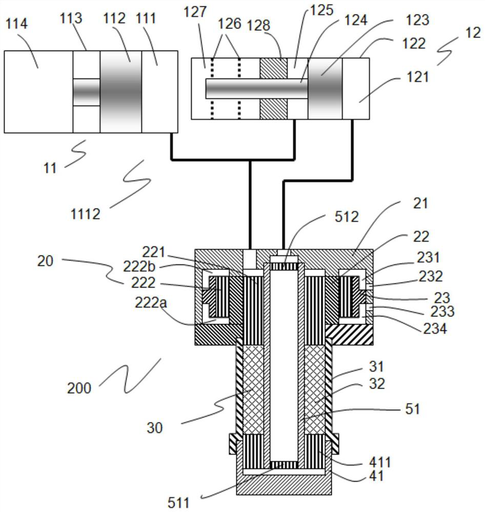
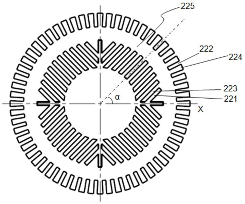
[0034] A heat exchanger includes such as figure 2 In the shown heat exchange body 22, four fan-shaped areas are arranged inside the heat exchange body 22 along the circumferential direction, and each fan-shaped area is provided with a plurality of mutually parallel inner fins 223 and a plurality of mutually parallel heat exchanger internal fins. Runner 221.

[0035]Wherein, the heat exchange body 22 includes a ring-shaped heat exchange body wall 225, the inner side of the heat exchange body wall 225 is arranged with a plurality of inner fins 223 along the circumferential direction, and a heat exchanger is formed between two adjacent inner fins 223. In the inner runner 221 , in each sector, two adjacent inner fins 223 are parallel to each other, and two adjacent inner runners 221 of the heat exchanger are parallel to each other.

[0036] In the 4 sectors, the included angle α between the flow channel 221 in the heat exchanger and the axial section of the heat exchange body 22...

Embodiment 2

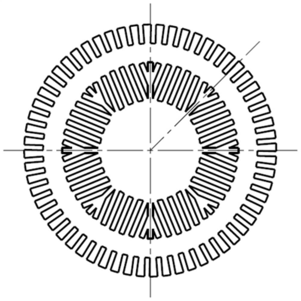
[0042] A heat exchanger includes such as image 3 In the heat exchange body 22 shown, eight sectors are arranged in the interior of the heat exchange body 22 along the circumferential direction, and each sector is provided with a plurality of mutually parallel inner fins 223 and a plurality of mutually parallel inner fins 223 . Runner 221. All the other are with embodiment 1.

[0043] The purpose of dividing into more sectors is to make the heat flux density of the heat exchange body wall 225 more uniform in the circumferential direction, because in each sector, the arrangement of the fins in the circumferential direction is uneven, so at different angles The heat flux is different, and the temperature distribution is also different. If there are too few sectors, the non-uniformity will be large; if there are too many sectors, the radial non-uniformity of the airflow will be large.

Embodiment 3

[0045] In this embodiment, three fan-shaped regions are arranged inside the heat exchange body 22 along the circumferential direction, and the rest are the same as in Embodiment 2.

[0046] Existing heat exchangers such as Figure 4 , Figure 5 As shown, for a conventional heat exchanger, on the outside of the heat exchanger, water flows from the side (such as from the left to the right), and is heated during the flow, so the temperature on the left and right is different. Similarly, it will cause the left and right imbalance of the regenerator, which will cause uneven flow; the flow area inside the heat exchanger is evenly distributed from the inside to the outside, so the flow channel area per unit cross-sectional area decreases from the inside to the outside, causing Regenerator radial airflow distribution is uneven. This problem is not very serious when the heat exchanger is small in diameter, because the aspect ratio is large at this time, and the inlet effect disappears...


PUM


Abstract

The invention relates to a heat exchanger and a pulse tube refrigerator containing the heat exchanger. The heat exchanger includes a heat exchange body, and the inside of the heat exchange body is arranged with a plurality of fan-shaped areas along the circumferential direction, and a plurality of fan-shaped areas are arranged in the fan-shaped area. Inner fins parallel to each other and a plurality of inner runners in the heat exchanger parallel to each other. Compared with the prior art, the present invention divides the interior of the heat exchange body into a plurality of fan-shaped areas, and makes the inner flow channels of the heat exchanger in each fan-shaped area parallel to each other, so as to ensure the air flow per unit area from the outside to the inside The total area of ​​the channels is the same, which solves the problem of uneven radial airflow when the gas reaches the regenerator; by setting the outer fins along the axial direction on the outside of the heat exchange body wall, and setting the inlet groove and outlet respectively on the outside of the collector The groove connects it with the outer flow channel of the heat exchanger. After the fluid is evenly distributed through the inlet groove, it flows axially and absorbs heat, which ensures that the temperature of the helium is uniform in the circumferential direction, and solves the problem that the heat exchanger is difficult to arrange axially due to the short axial length. Cooling, the problem that the gas temperature at the inlet of the regenerator is not uniform along the circumference.

Description

technical field [0001] The invention belongs to the technical field of pulse tube refrigerators, and relates to a heat exchanger and a pulse tube refrigerator containing the heat exchanger. Background technique [0002] In regenerative refrigerators (such as Stirling refrigerators and pulse tube refrigerators), the working medium is generally helium, and the heat exchanger generally uses a copper column as a heat exchange body, which is cut out inside the copper column with a wire cutting machine. grooves, and the remaining part between the grooves forms the inner fins, and the outer fins are processed on the outside of the copper pillars. Water or other fluids are passed between the outer fins to cool the helium gas passed into the tank. Due to the need for small flow resistance, the general heat exchanger is relatively short, and most of them cut out ring-shaped outer fins on the outside of the copper column. Water passes through one side and flows out from the other side...

Claims


Application Information

Patent Timeline
Patent Type & Authority Patents(China)
IPC IPC(8): F25B9/14
CPCF25B9/145F25B2309/1412
Inventor 朱绍伟
Owner TONGJI UNIV
Learn More