Mounting assembly for a heat exchanger device

A technology of heat exchange device and assembly, applied in the direction of heat exchange equipment, heat exchanger type, heat exchanger shell, etc.

Active Publication Date: 2009-09-16
BEHR GMBH & CO KG
View PDF7 Cites 0 Cited by
  • Summary
  • Abstract
  • Description
  • Claims
  • Application Information

AI Technical Summary

Problems solved by technology

This raises the question of how these different heat exchange devices can be connected, or how one device can be connected to another

Method used


Image

  • Mounting assembly for a heat exchanger device
  • Mounting assembly for a heat exchanger device
  • Mounting assembly for a heat exchanger device

Examples


Embodiment Construction

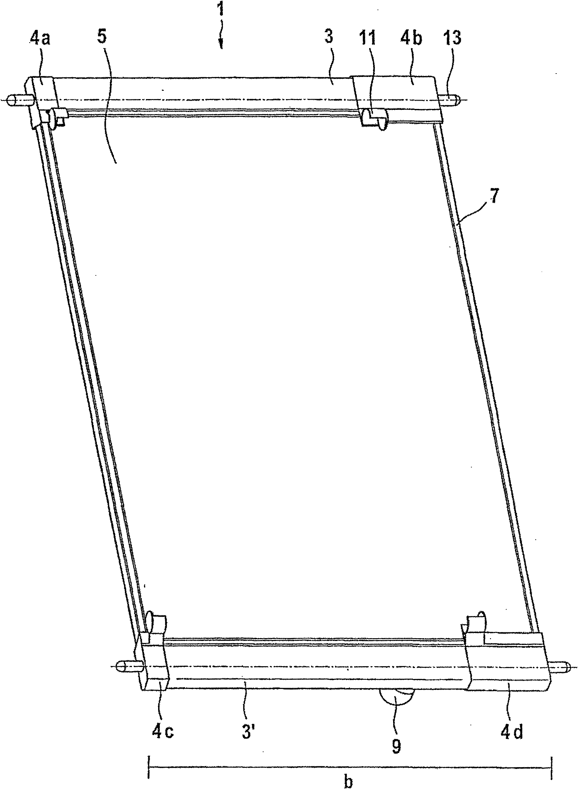
[0064] figure 1 It is a perspective view of the assembly assembly 1 according to the present invention. In the figures, reference numeral 3 refers to a first header and / or distribution pipe, and reference numeral 3' refers to a second header and / or distribution pipe. Reference numeral 5 indicates the area occupied by the arrangement of various piping components (not shown in the figure). Here, the line elements are arranged along the width b. Reference numerals 4a, 4b, 4c and 4d refer to the mounting elements in the upper left corner, upper right corner, lower left corner and lower right corner in turn. In this embodiment, the mounting elements have projections 13 which protrude laterally out of the device 1 in the direction b. Reference numeral 11 denotes a positioning element of another device (not shown) through which fluid flows or receives fluid. Reference numeral 7 denotes a frame member.

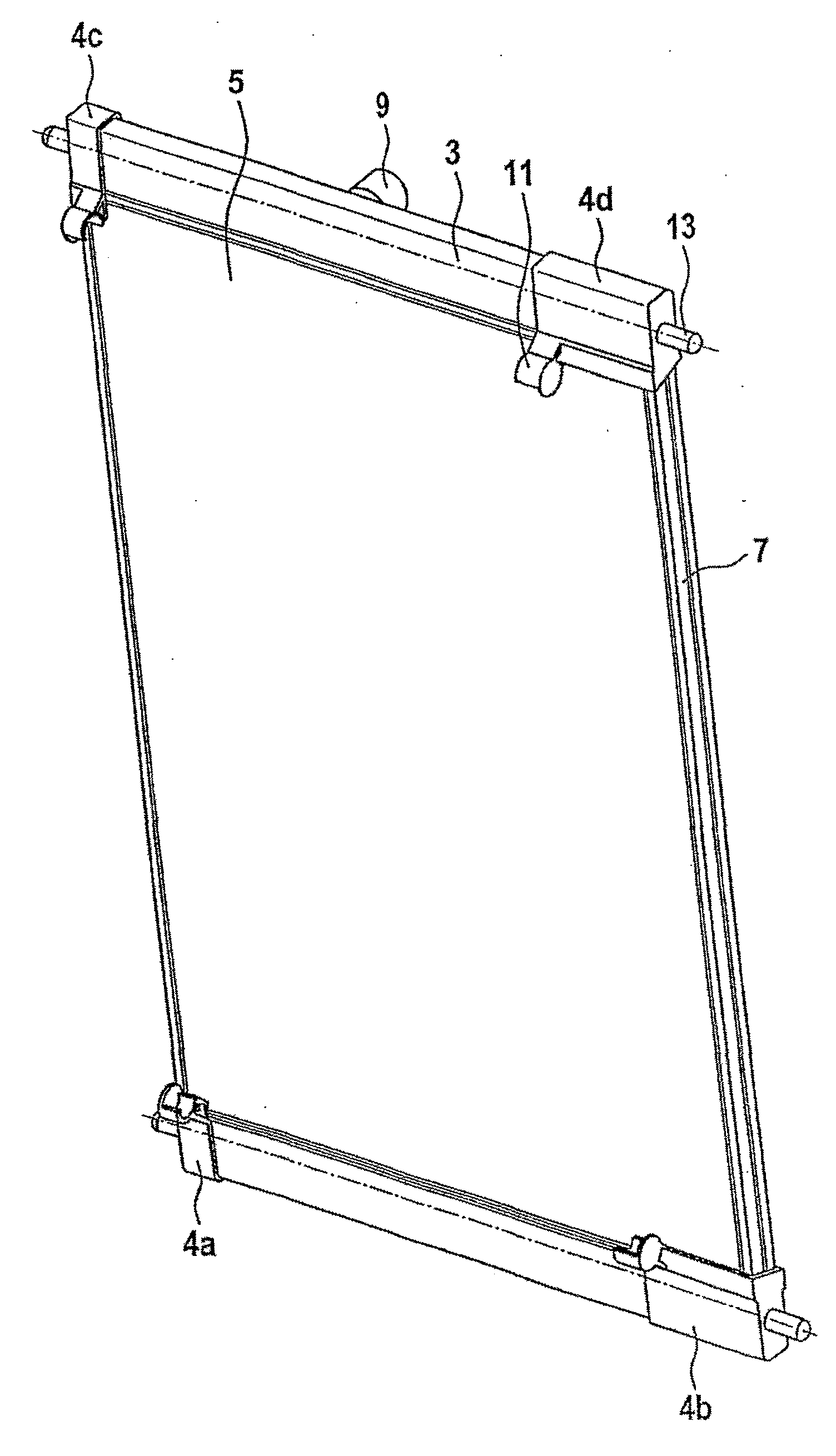
[0065] figure 2 for figure 1 Another perspective view of the assembly sho...


PUM


Abstract

The invention relates to a mounting assembly (1) for a heat exchanger device, in particular for motor vehicles and to an additional unit that is traversed by or holds a fluid and that can be connected to said assembly. The assembly comprises a plurality of flow devices with a predefined length, which are arranged essentially in parallel along a predefined width, each having at least two connection sections at their ends, in addition to at least two collection and / or distribution pipes (3, 3') with a predefined length, which are located on the respective end connection sections of the flow devices in such a way that a medium can flow between the flow devices and the collection and / or distribution pipes (3, 3'). At least one mounting unit (11) for the additional unit that is traversed by or holds a fluid is located on at least one collection and / or distribution pipe (3, 3').

Description

technical field [0001] The invention relates to an assembly for at least a first and at least a further vehicle heat exchanger. Background technique [0002] Different heat exchange devices such as condensers or radiators are often used in automobiles. A problem thus arises as to how these different heat exchange devices can be connected, or how one device can be connected to another. Due to the inherently limited installation space, this connection or connection should take place in a space-saving and cost-effective manner. Contents of the invention [0003] The object of the invention is to improve the connection between different heat exchange devices. [0004] According to the invention, the above object is achieved by an assembly of a first heat exchanging device for use in a motor vehicle and a second heat exchanging device which can be connected to the assembly and be passed through or receive a fluid by a fluid, this assembly It has: a plurality of pipeline elem...

Claims


Application Information

Patent Timeline
Patent Type & Authority Patents(China)
IPC IPC(8): F28D1/04F28F9/00
CPCF28F9/002F28D1/0408
Inventor 佩德罗·冈萨雷斯雷歇
Owner BEHR GMBH & CO KG
Why Eureka
Try Eureka