


Quick Research
Generate reliable direction feasibility study reports for your R&D in just a few steps.

Technical Q&A
Discover and master advanced knowledge NOW. Basics, ideas, possibilities, all at once.

Find Solutions
As an expert in R&D theories, this can generate solutions to your technical problems instantly.

Evaluate Feasibility
Analyze your overall solution with one click, know your potential R&D risks in advance.

Monitor Landscape
Get weekly tech updates, stay abreast of the latest tech innovations and key insights.
Heat exchanger and pulse tube refrigeration machine with heat exchanger
A technology of pulse tube refrigerators and heat exchangers, which is applied in refrigerators, gas cycle refrigerators, refrigeration and liquefaction, etc., can solve the problems of reduced heat recovery efficiency, small length-to-diameter ratio, and failure of refrigerators to refrigerate, so as to achieve improvement. Uniformity problem, the effect of circumferential uniformity of temperature
- Summary
- Abstract
- Description
- Claims
- Application Information
AI Technical Summary
Problems solved by technology
Method used
Image

Examples
Embodiment 1
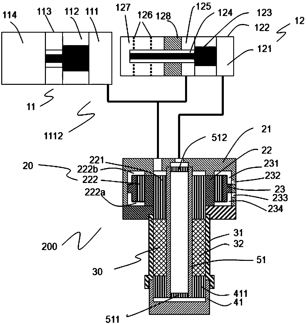
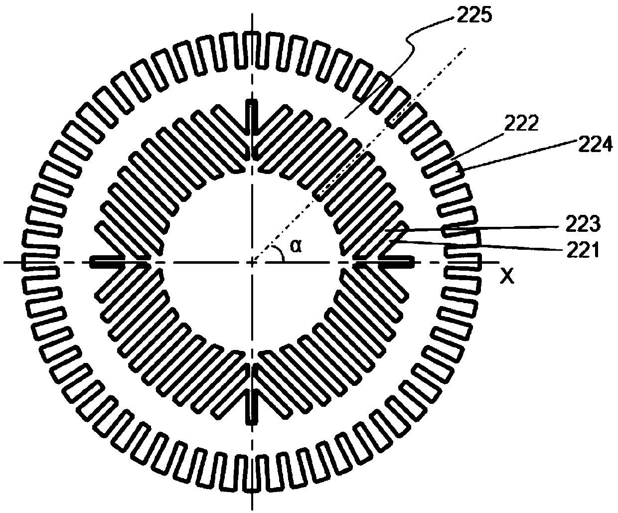
[0034] A heat exchanger includes such as figure 2 In the shown heat exchange body 22, four fan-shaped areas are arranged inside the heat exchange body 22 along the circumferential direction, and a plurality of mutually parallel inner fins 223 and a plurality of mutually parallel inner fins 223 are arranged in each fan-shaped area. Runner 221.
[0035]Wherein, the heat exchange body 22 includes a ring-shaped heat exchange body wall 225, the inner side of the heat exchange body wall 225 is arranged with a plurality of inner fins 223 along the circumferential direction, and a heat exchanger is formed between two adjacent inner fins 223. In the inner runner 221 , in each sector, two adjacent inner fins 223 are parallel to each other, and two adjacent inner runners 221 of the heat exchanger are parallel to each other.
[0036] In the 4 sectors, the included angle α between the flow channel 221 in the heat exchanger and the axial section of the heat exchange body 22 as a reference...
Embodiment 2
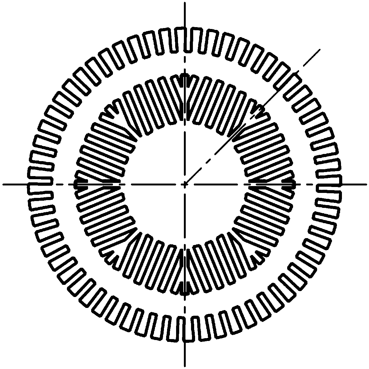
[0042] A heat exchanger includes such as image 3 In the heat exchange body 22 shown, eight sectors are arranged in the interior of the heat exchange body 22 along the circumferential direction, and each sector is provided with a plurality of mutually parallel inner fins 223 and a plurality of mutually parallel inner fins 223 . Runner 221. All the other are with embodiment 1.
[0043] The purpose of dividing into more sectors is to make the heat flux density of the heat exchange body wall 225 more uniform in the circumferential direction, because in each sector, the arrangement of the fins in the circumferential direction is uneven, so at different angles The heat flux is different, and the temperature distribution is also different. If there are too few sectors, the non-uniformity will be large; if there are too many sectors, the radial non-uniformity of the airflow will be large.
Embodiment 3
[0045] In this embodiment, three fan-shaped regions are arranged inside the heat exchange body 22 along the circumferential direction, and the rest are the same as in Embodiment 2.
[0046] Existing heat exchangers such as Figure 4 , Figure 5 As shown, for a conventional heat exchanger, on the outside of the heat exchanger, water flows from the side (such as from the left to the right), and is heated during the flow, so the temperature on the left and right is different. Similarly, it will cause the left and right imbalance of the regenerator, which will cause uneven flow; the flow area inside the heat exchanger is evenly distributed from the inside to the outside, so the flow channel area per unit cross-sectional area decreases from the inside to the outside, causing Regenerator radial airflow distribution is uneven. This problem is not very serious when the heat exchanger is small in diameter, because the aspect ratio is large at this time, and the inlet effect disappears...
PUM
 Abstract
Description
Claims
Application Information
 - R&D Engineer
- R&D Manager
- IP Professional
- Industry Leading Data Capabilities
- Powerful AI technology
- Patent DNA Extraction
Browse by: Latest US Patents, China's latest patents, Technical Efficacy Thesaurus, Application Domain, Technology Topic, Popular Technical Reports.
© 2024 PatSnap. All rights reserved.Legal|Privacy policy|Modern Slavery Act Transparency Statement|Sitemap|About US| Contact US: help@patsnap.com