Control method of smoke discharge fan of continuos annealing furnace
A continuous annealing furnace and exhaust fan technology, applied in pump control, heat treatment process control, furnace and other directions, can solve problems such as large pressure fluctuations in the gas collection chamber, unstable operation of the exhaust fan, and motor damage.
- Summary
- Abstract
- Description
- Claims
- Application Information
AI Technical Summary
Problems solved by technology
Method used
Image
Examples
Embodiment 1
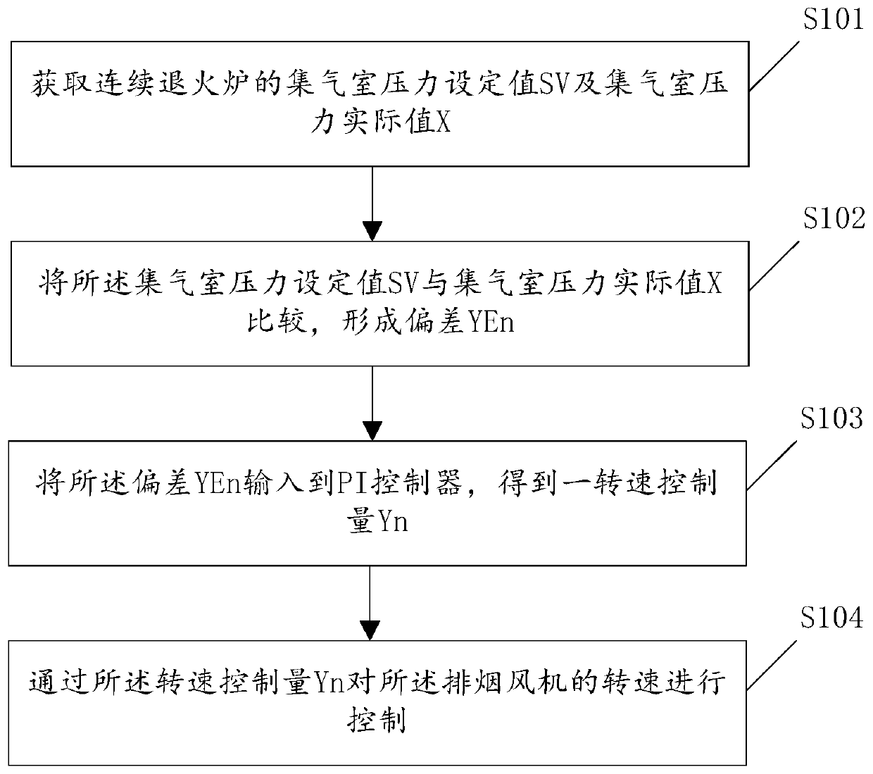
[0030] Such as figure 1 As shown, this embodiment provides a method for controlling the exhaust fan of a continuous annealing furnace, including:
[0031] S101: Obtain the set value SV of the pressure of the gas collection chamber and the actual value X of the pressure of the gas collection chamber of the continuous annealing furnace; specifically, the set value SV of the pressure of the gas collection chamber is set to 1500pa.
[0032] S102: Comparing the set value SV of the pressure of the air collection chamber with the actual value X of the pressure of the air collection chamber to form a deviation YEn;
[0033] S103: Input the deviation YEn into the PI controller to obtain a speed control variable Yn;
[0034] S104: Control the rotation speed of the smoke exhaust fan by the rotation speed control amount Yn.
[0035] It should be noted that the rotational speed control variable Yn is used to control the rotational speed of the smoke exhaust fan, and the rotational speed ...
Embodiment 2
[0070] Such as Figure 6 As shown, based on the same inventive concept, the application provides a control system for a continuous annealing furnace exhaust fan, including:
[0071] The obtaining module 201 is used to obtain the set value SV of the pressure of the gas collection chamber and the actual value X of the pressure of the gas collection chamber of the continuous annealing furnace;
[0072] A comparison module 202, configured to compare the set value SV of the pressure of the air collection chamber with the actual value X of the pressure of the air collection chamber to form a deviation YEn;
[0073] The input module 203 is used to input the deviation YEn into the PI controller to obtain a rotational speed control value Yn;
[0074] The control module 204 is configured to control the rotation speed of the smoke exhaust fan through the rotation speed control value Yn.
[0075] As an optional embodiment, the input module 203 includes:
[0076] The determination sub-m...
Embodiment 3
[0090] A computer storage medium, on which a computer program is stored, and when the computer program is executed by a processor, the following steps are implemented:
[0091] Obtain the set value SV of the pressure of the plenum chamber and the actual value X of the pressure of the plenum chamber of the continuous annealing furnace; compare the set value SV of the pressure of the plenum chamber with the actual value X of the pressure of the plenum chamber to form a deviation YEn; The deviation YEn is input to the PI controller to obtain a rotational speed control variable Yn; the rotational speed of the exhaust fan is controlled by the rotational speed control variable Yn.
[0092] In a specific implementation process, when the program is executed by a processor, any implementation manner in the first embodiment above may be implemented.
[0093] The above-mentioned technical solutions in the embodiments of the present application have at least the following technical effect...
PUM
 Abstract
Description
Claims
Application Information
 - R&D
- Intellectual Property
- Life Sciences
- Materials
- Tech Scout
- Unparalleled Data Quality
- Higher Quality Content
- 60% Fewer Hallucinations
Browse by: Latest US Patents, China's latest patents, Technical Efficacy Thesaurus, Application Domain, Technology Topic, Popular Technical Reports.
© 2025 PatSnap. All rights reserved.Legal|Privacy policy|Modern Slavery Act Transparency Statement|Sitemap|About US| Contact US: help@patsnap.com


