
Copper rod

A technology of copper rods and round rods, applied in glass manufacturing equipment, glass cutting devices, hand-held tools, etc., can solve problems such as glass cutting failure, glass cutter head falling, wrist pain, etc., and achieve the effect of light and labor-saving operation

Active Publication Date: 2019-12-17
HEFEI EDISON PRECISION MACHINERY CO LTD
View PDF5 Cites 0 Cited by
  • Summary
  • Abstract
  • Description
  • Claims
  • Application Information

AI Technical Summary

Problems solved by technology

[0003] When using a copper rod connected by a glass knife, when hitting the surface of the structure to be cut, it is necessary to continuously raise the hand to drive the whole reciprocating movement to knock. The operation wrist is sore, and the glass cannot be cut ideally. At the same time, the glass cutter head will fall during use after the copper rod is used to fix the glass cutter head, which will damage the nearby objects, and is not conducive to the glass cutter head. protection of

Method used


Image

  • Copper rod
  • Copper rod
  • Copper rod

Examples


Embodiment Construction

[0023] In order to make the purpose, features and advantages of the present invention more obvious and understandable, the technical solutions in the embodiments of the present invention will be clearly and completely described below in conjunction with the accompanying drawings in the embodiments of the present invention. Obviously, the following The described embodiments are only some, not all, embodiments of the present invention. Based on the embodiments of the present invention, all other embodiments obtained by persons of ordinary skill in the art without making creative efforts belong to the protection scope of the present invention.

[0024] The technical solutions of the present invention will be further described below in conjunction with the accompanying drawings and through specific implementation methods.

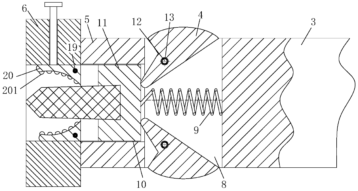
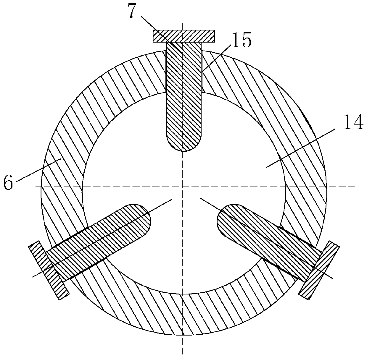
[0025] see Figure 1-6 As shown, a copper rod includes a copper round rod 3, a pressing structure, a guide structure, a cutter head fixing structure and a ret...


PUM


Abstract

The invention specifically relates to a copper rod, belonging to the technical field of copper rods. The copper rod comprises a copper cover, antiskid lines, a copper round rod, a finger pressing plate, a round copper plate, a round copper block, crosshead bolts, a square-mouth through hole, a reset spring, a square-mouth groove, a rectangular guide block, a movable pin, a first torsion spring, acolumn groove, a threaded hole, a second torsion spring, a shaft rod and a single-groove copper wheel. The copper rod is reasonable in design, and glass cutter heads with connecting structures of different specifications and sizes can be fixedly connected by adjusting the distances among the three crosshead bolts, so the function of knocking a to-be-cut plate structure in a reciprocating manner via a glass tool bit is realized, and scrapped plate structures at one sides of scratches can be conveniently knock off; and a thin wire which is wound on the single-groove copper wheel and soaked withprinting ink is pulled out of the copper cover to approach the surface of a corresponding structure in a linear mode, then two ends of the thin wire are fixed, and the thin wire is loosened and pulledupwards for snapping of the thin wire, so the auxiliary function of drawing a straight line on the surface of the corresponding structure is achieved.

Description

technical field [0001] The invention belongs to the technical field of copper rods, in particular to a copper rod. Background technique [0002] A glass knife refers to a tool used to cut glass. Usually, the part of a glass knife used for cutting is made of diamond or alloy material that is harder than glass. This part is at the tip of the knife. The knife can be divided into diamond glass knife and alloy roller glass knife. It is suitable for cutting flat glass with a thickness of 1-8 mm. It is an indispensable glass cutting tool for decoration and building materials industries. [0003] When using a copper rod connected by a glass knife, when hitting the surface of the structure to be cut, it is necessary to continuously raise the hand to drive the whole reciprocating movement to knock. The operation wrist is sore, and the glass cannot be cut ideally. At the same time, the glass cutter head will fall during use after the copper rod is used to fix the glass cutter head, wh...

Claims


Application Information

Patent Timeline
IPC IPC(8): C03B33/12B25G3/26
CPCC03B33/12B25G3/26
Inventor 周俊满张健杨鑫
Owner HEFEI EDISON PRECISION MACHINERY CO LTD
Learn More