
Multifunctional mode circuit and wireless power transfer system

A wireless power transmission, mode circuit technology, applied in circuits, circuit devices, transformer/inductor coils/windings/connections, etc., can solve problems such as the large difference in chassis height and the difficulty in meeting the air gap range, and achieve an increase in the coupling range. Larger, larger air gap range, and the effect of increasing the application range

Active Publication Date: 2020-12-04
上海道充科技有限公司
View PDF7 Cites 0 Cited by
  • Summary
  • Abstract
  • Description
  • Claims
  • Application Information

AI Technical Summary

Problems solved by technology

However, in practical applications, such as wireless charging of electric vehicles, due to the different models of vehicles, the height of the chassis varies greatly, and the air gap range of 40mm is difficult to meet the actual requirements.

Method used


Image

  • Multifunctional mode circuit and wireless power transfer system
  • Multifunctional mode circuit and wireless power transfer system
  • Multifunctional mode circuit and wireless power transfer system

Examples


Embodiment Construction

[0047] Combine below Figure 5 to Figure 11 , the multi-function mode circuit of the present invention will be described in detail.

[0048] A multifunctional mode circuit of the present invention includes a wireless power transmission coil with M primary coils and M external terminals, and M≥2, wherein the M primary coils are connected in series in sequence, and every two adjacent primary coils There are coil connection switches between the side coils, and at the same time, the two ends of each coil connection switch are respectively connected to two adjacent external terminals through the terminal connection switch, and the M primary side coils are also respectively connected to M external terminals through compensation capacitors. The terminals are connected in one-to-one correspondence. Therefore, by adjusting the switch state of each switch, the circuit can be in a variety of different working modes.

[0049] exist Figure 5 In the illustrated embodiment, the aforement...


PUM

PropertyMeasurementUnit
capacitanceaaaaaaaaaa

Abstract

The invention discloses a multifunctional mode circuit and a wireless power transmission coil, and belongs to the technical field of wireless power transmission. The multifunctional mode circuit disclosed by the invention comprises a wireless power transmission coil with M primary side coils and M external terminals, wherein M is greater than or equal to 2; the M primary side coils are sequentially connected in series, every two adjacent primary side coils are provided with a coil connecting switch therebetween, meanwhile, two ends of each coil connecting switch are connected with two adjacentexternal terminals through terminal connecting switches, and the M primary side coils are further connected with the M external terminals in a one-to-one correspondence mode through compensation capacitors. By virtue of different adjustment of the switches, multiple working modes can be realized. The multifunctional mode circuit can be used for adjusting the input impedance of wireless power transmission, so that the wireless power transmission can effectively realize power transmission in a large coupling range.

Description

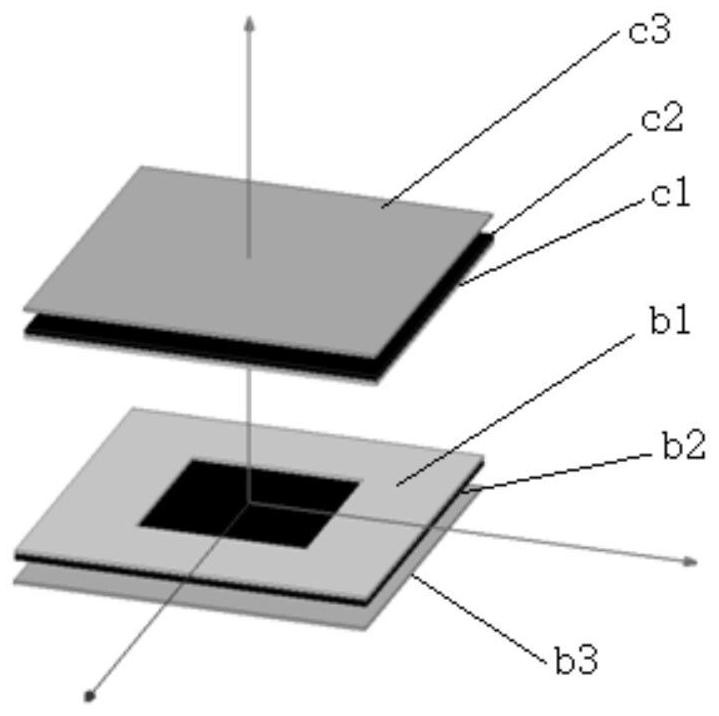
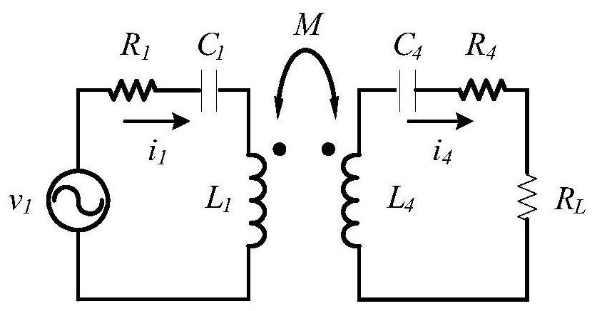
technical field [0001] The invention relates to the technical field of wireless power transmission, in particular to a multifunctional mode circuit and a wireless power transmission system. Background technique [0002] Such as figure 1 As shown, the existing wireless power transmission coil includes a primary structure and a secondary structure, wherein the primary structure includes a primary coil layer b1, a magnetic core layer b2 and an aluminum plate shielding layer b3, and the secondary structure includes a secondary coil layer c1, magnetic core layer c2 and aluminum plate shielding layer c3, wherein the primary side coil layer b1 includes a primary side coil L 1 , the secondary coil layer c1 includes a secondary coil L 4 . Table 1 lists the figure 1 Parameter details of the China Radio Power Transmission Coil in an actual application scenario (the inductance and mutual inductance are obtained by finite element simulation): [0003] Table 1 [0004] [0005] ...

Claims


Application Information

Patent Timeline
Patent Type & Authority Patents(China)
IPC IPC(8): H02J50/40H02J50/12H01F38/14H01F27/28
CPCH01F27/288H01F38/14H02J50/12H02J50/40
Inventor 钟文兴叶宏峰
Owner 上海道充科技有限公司
Learn More