Eureka AIR delivers breakthrough ideas for toughest innovation challenges, trusted by R&D personnel around the world.

Rapid state detection system and detection method

A fast state and detection system technology, applied in the direction of signal transmission systems, instruments, electrical components, etc., can solve the problems of equipment application environment restrictions, inconvenient battery replacement, cumbersome process, etc., to reduce device complexity and use costs, reduce The probability of danger, the effect of simple and convenient working process

Pending Publication Date: 2019-12-13
杨田荣
View PDF0 Cites 2 Cited by
  • Summary
  • Abstract
  • Description
  • Claims
  • Application Information

AI Technical Summary

Problems solved by technology

[0002] Most of the state detection in the prior art relies on active devices, that is, the sensor must continue to supply power. For some equipment that is not used at ordinary times, the active device needs to be additionally equipped with a power supply circuit. The supply increases the complexity and cost, and it is necessary to prevent dangers such as leakage of electricity, and the method of using a built-in battery is not convenient for battery replacement, and the power needs to be monitored at all times to prevent the battery from running out and overcharging the battery. Explosions caused by over-discharge and leakage of liquid may cause corrosion problems to devices
For data transmission, additional interfaces need to be set up, which makes the process cumbersome, and setting too many interfaces will cause strict restrictions on the applicable application environment of the device, which will affect the use

Method used


Image

  • Rapid state detection system and detection method
  • Rapid state detection system and detection method
  • Rapid state detection system and detection method

Examples


Embodiment Construction

[0035] The following will clearly and completely describe the technical solutions in the embodiments of the present invention with reference to the accompanying drawings in the embodiments of the present invention. Obviously, the described embodiments are only some, not all, embodiments of the present invention. Based on the embodiments of the present invention, all other embodiments obtained by persons of ordinary skill in the art without making creative efforts belong to the protection scope of the present invention.

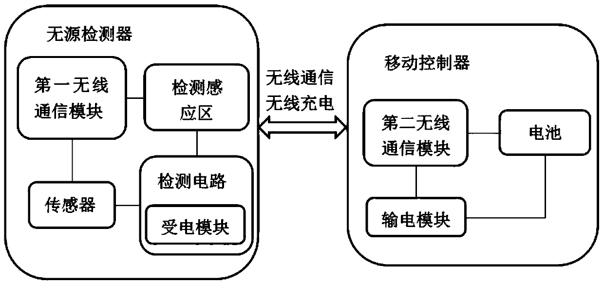
[0036] see figure 1 , figure 1 It is the block diagram of the detection system.

[0037] A fast state detection system including passive detectors and motion controllers.

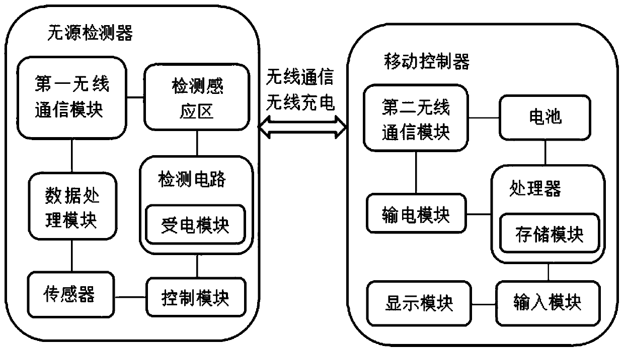
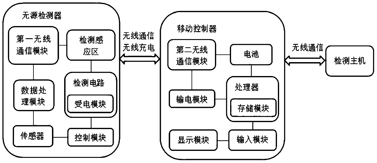
[0038] The passive detector includes a detection sensing area, a detection circuit, a sensor and a first wireless communication module, the detection sensing area, the detection circuit, the sensor and the first wireless communication module are electrically connected, and the sensor is f...


PUM


Abstract

A rapid state detection system comprises a passive detector and a mobile controller, wherein the passive detector comprises a detection induction region, a detection circuit, a sensor and a first wireless communication module, the detection induction region, the detection circuit, the sensor and the first wireless communication module are electrically connected, the sensor is fixedly arranged on adetection point and is used for acquiring an original parameter of the detection point, the detection circuit is used for acquiring a power acceptance module of an energy source, the first wireless communication module is used for sending the original parameter, the mobile controller is used for driving and controlling the passive detector and acquiring the original parameter, the mobile controller comprises a second wireless communication module, a battery and a power transmission module, the second wireless communication module is used for being in communication connection with the first wireless communication module by wireless communication, and the power transmission module is matched with the power acceptance module. The invention provides the rapid state detection system and detection method, control and data exchange are performed between the passive detector and the mobile controller by wireless communication, and the rapid state detection system is high in safety, rapid in detection speed and high in result accuracy.

Description

【Technical field】 [0001] The invention relates to the technical field of state detection, in particular to a fast state detection system and detection method. 【Background technique】 [0002] Most of the state detection in the prior art relies on active devices, that is, the sensor must continue to supply power. For some equipment that is not used at ordinary times, the active device needs to be additionally equipped with a power supply circuit. The supply increases the complexity and cost, and it is necessary to prevent dangers such as leakage of electricity, and the method of using a built-in battery is not convenient for battery replacement, and the power needs to be monitored at all times to prevent the battery from running out and overcharging the battery. The explosion caused by over-discharge and the leakage of liquid will easily cause corrosion problems to the device. For data transmission, additional interfaces need to be set, which makes the process cumbersome, and...

Claims


Application Information

Patent Timeline
IPC IPC(8): G08C17/02H02J50/20
CPCG08C17/02H02J50/20
Inventor 杨田荣
Owner 杨田荣
Why Eureka
Eureka Blog
Learn More