
Heater for heating network

A heating net heater, filter net technology, applied in the direction of heat exchanger shell, indirect heat exchanger, heat exchanger type, etc., can solve the problem of reducing the effective utilization time of the heater, affecting the efficiency of hot water production, and the inner wall of the tube bundle being easily knotted. Scale and other problems, to achieve the effect of reducing the probability of tube bundle blockage and scaling, reducing the probability of impurities blocking the mesh holes, and reducing the number of cleanings

Active Publication Date: 2019-12-13
SHANDONG GUOSHUN PRESSURE VESSEL
View PDF8 Cites 1 Cited by
  • Summary
  • Abstract
  • Description
  • Claims
  • Application Information

AI Technical Summary

Problems solved by technology

[0004] The above existing technical solutions have the following defects: since the return water of the heating network will contain impurities such as metal oxides, crushed sand or sediment, when the water flows in the tube bundle, the impurities will cause the tube bundle to block; Impurities deteriorate the water quality, making it easy to scale on the inner wall of the tube bundle, thereby reducing the heat exchange efficiency; when the tube bundle is blocked or there is too much scaling, it is necessary to stop the operation of the heater and use special cleaning equipment to clean the tube bundle , reducing the effective utilization time of the heater, inevitably affecting the hot water production efficiency

Method used


Image

  • Heater for heating network
  • Heater for heating network
  • Heater for heating network

Examples


Embodiment Construction

[0039] The present invention will be described in further detail below in conjunction with the accompanying drawings.

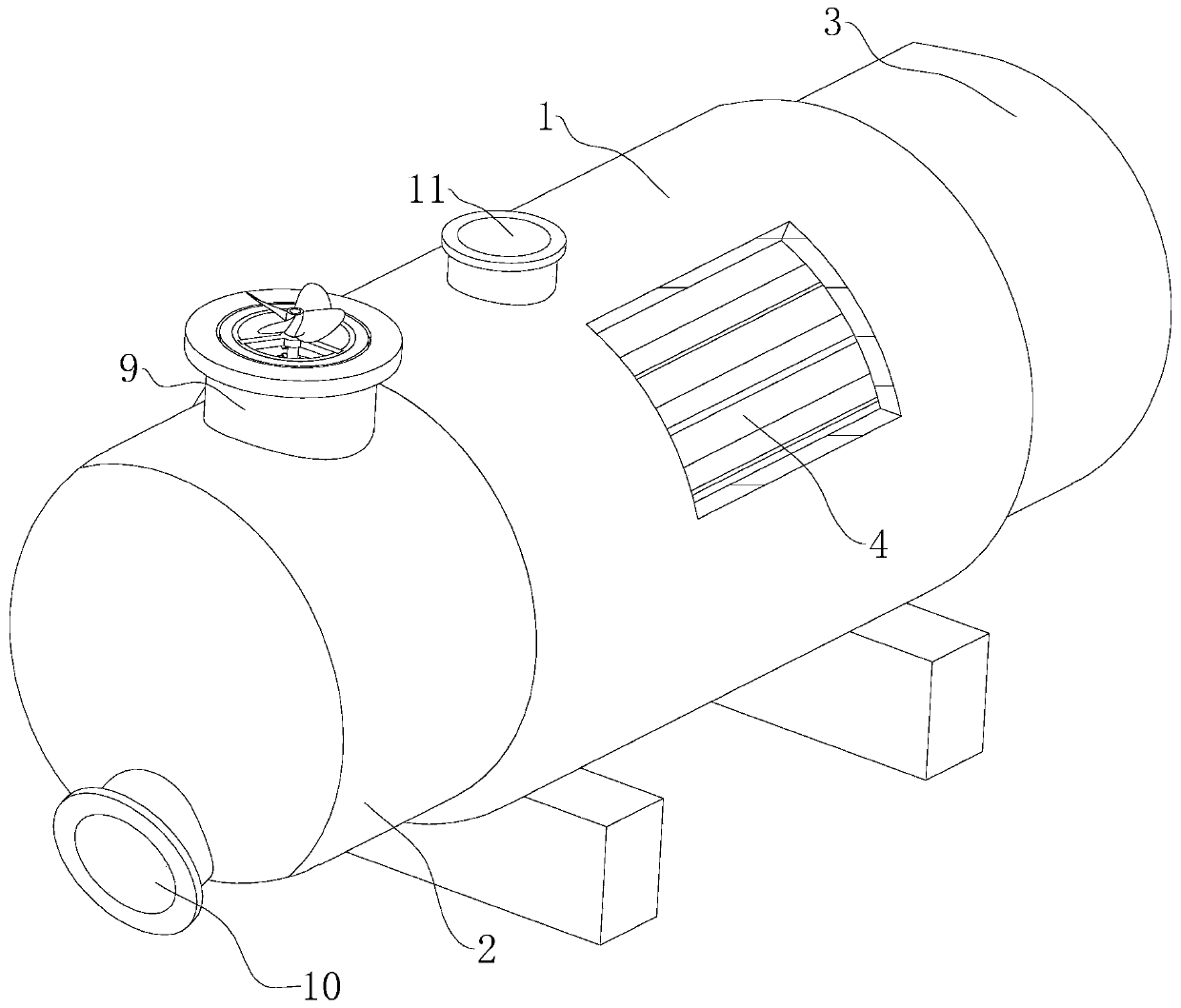
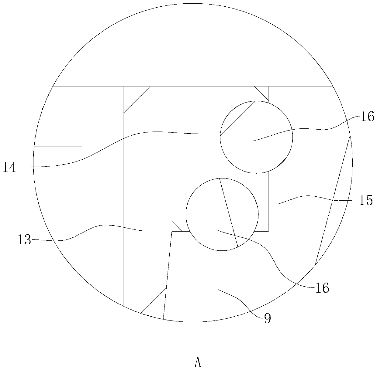
[0040] refer to figure 1 with 2 , is a heating network heater disclosed in the present invention, comprising a hollow housing 1, the housing 1 is cylindrical; the two ends of the housing 1 are respectively fixed with a front pipe box 2 and a rear pipe box 3; Tube plates 5 are respectively fixed at both ends of 1 to isolate the shell 1 from the internal space of the front end tube box 2 and the rear end tube box 3; a tube bundle 4 is also arranged in the shell 1, and the tube bundle 4 is arranged in a U shape, and the Pass through the two tube sheets 5 and be welded and fixed on the two tube sheets 5; wherein, the open ends of the tube bundles 4 are all located in the front end tube box 2. A partition 6 is fixed inside the front end tube box 2 along the axis of the shell 1, and the partition 6 is fixed to the inner wall of the front end tube box 2 and the tu...


PUM


Abstract

The invention relates to a heater for heating network. The heater for heating network comprises a shell and a front end pipe box and a rear end pipe box; the front end pipe box and the rear end pipe box are arranged at the two ends of the shell; pipe bundles are arranged in the shell; a partition plate is arranged in the front end pipe box along the axis of the shell and the front end pipe box isdivided into an upper water inlet cavity and a lower water outlet cavity; the upper end of the water inlet cavity communicates with a water inlet pipe connecting pipe; the lower end of the water outlet cavity communicates with a water outlet pipe connecting pipe; the upper end of the shell is provided a steam inlet connecting pipe; the lower end of the shell is provided with a drain outlet connecting pipe; a filter screen is arranged in the water inlet pipe connecting pipe; the filter screen is cylindrical with an opening arranging at the upper end; the upper end of the filter screen is rotationally connected in the water inlet pipe connecting pipe and the lower end of the filter screen extends into the water inlet cavity; and a driving part for driving the filter screen to rotate is arranged in the water inlet pipe connecting pipe. The heater for heating network has the effects that the water medium is filtered, impurities are reduced from entering the pipe bundles, the probability ofblockage and scaling of the pipe bundles is reduced so that the cleaning times are further reduced, the utilization efficiency of the heater is guaranteed to the greatest extent, and the production efficiency is improved.

Description

technical field [0001] The invention relates to the technical field of boiler heating, in particular to a heating network heater. Background technique [0002] At present, the heat network heater is the key equipment of the heat network system and one of the main auxiliary equipment of the thermal power plant. Circulating water to meet heating user requirements. [0003] The existing authorized announcement is CN103868379B, which discloses a heat-mixing heat network heater, including a left tube box and a right tube box, and the tube plate shell arranged in the middle of the left tube box and the right tube box is welded, and is arranged on the tube plate The tube bundle inside the shell is welded, and the tube bundle is divided into three areas, namely the low resistance area near the upper and lower ends of the shell, and the high resistance area near the center line of the tube bundle, which is set between the high resistance area and the low resistance area. The transi...

Claims


Application Information

Patent Timeline
Patent Type & Authority Applications(China)
IPC IPC(8): F28D7/00F28F19/01F28F9/02F01K17/02F16H1/32B01D33/067B01D33/80
CPCB01D5/0009B01D33/067B01D33/80F01K17/02F16H1/32F28D7/00F28F9/02F28F19/01
Inventor 张绍庭张爱军刘青林赵至蓬李帅赵士栋
Owner SHANDONG GUOSHUN PRESSURE VESSEL
Learn More