


Quick Research
Generate reliable direction feasibility study reports for your R&D in just a few steps.

Technical Q&A
Discover and master advanced knowledge NOW. Basics, ideas, possibilities, all at once.

Find Solutions
As an expert in R&D theories, this can generate solutions to your technical problems instantly.

Evaluate Feasibility
Analyze your overall solution with one click, know your potential R&D risks in advance.

Monitor Landscape
Get weekly tech updates, stay abreast of the latest tech innovations and key insights.
Pipeline valve box and groove type wet processing equipment
A pipeline valve and pipeline technology, applied in mechanical equipment, pipeline systems, gas/liquid distribution and storage, etc., can solve the problems of operator injury, scattered valve settings, inconvenient operation, etc., achieve maintenance and repair safety, and prevent continuous , Reduce the effect of leakage hazards
- Summary
- Abstract
- Description
- Claims
- Application Information
AI Technical Summary
Problems solved by technology
Method used
Image


Examples
Embodiment 1
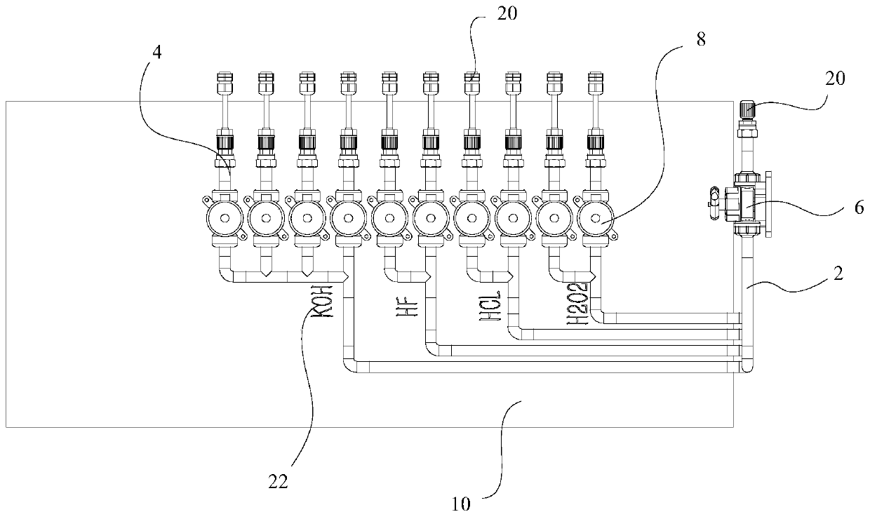
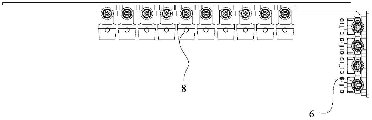
[0046] Such as Figure 1 to Figure 4 As shown, the first embodiment of the present invention provides a pipeline valve box including: a pipeline, a manual valve 6 , a pneumatic valve 8 and a box body 10 .
[0047] Wherein, the pipeline includes at least one supply pipeline 2, and each supply pipeline 2 communicates with at least one branch pipeline 4; the manual valve 6 is arranged on the supply pipeline 2; the pneumatic valve 8 is arranged on the branch pipeline 4; On the pipeline 2 and the branch pipeline 4 , the manual valve 6 and the pneumatic valve 8 are located in the box body 10 .
[0048] The present invention arranges the supply pipeline 2 and the branch pipeline 4 in the box body 10 through the arrangement of the pipeline, the manual valve 6, the pneumatic valve 8 and the box body 10, the manual valve 6 is arranged on the supply pipeline 2, and the pneumatic valve 8 is arranged on the branch pipeline. On the pipeline 4, the manual valve 6 and the pneumatic valve 8 t...
Embodiment 2
[0051] Such as Figure 1 to Figure 4 As shown, the first embodiment of the present invention provides a pipeline valve box including: a pipeline, a manual valve 6 , a pneumatic valve 8 and a box body 10 .
[0052] Wherein, the pipeline includes at least one supply pipeline 2, and each supply pipeline 2 communicates with at least one branch pipeline 4; the manual valve 6 is arranged on the supply pipeline 2; the pneumatic valve 8 is arranged on the branch pipeline 4; On the pipeline 2 and the branch pipeline 4 , the manual valve 6 and the pneumatic valve 8 are located in the box body 10 .
[0053] Further, the pipeline valve box further includes: a liquid leakage detection switch, which is arranged on at least one of the branch pipeline 4 , the supply pipeline 2 and the box body 10 .
[0054] In this embodiment, due to the sporadic nature of liquid leakage in the production process, there are usually no full-time personnel to observe whether there is liquid leakage in the pipe...
Embodiment 3
[0058] Such as Figure 1 to Figure 7 As shown, the first embodiment of the present invention provides a pipeline valve box including: a pipeline, a manual valve 6 , a pneumatic valve 8 and a box body 10 .
[0059] Wherein, the pipeline includes at least one supply pipeline 2, and each supply pipeline 2 communicates with at least one branch pipeline 4; the manual valve 6 is arranged on the supply pipeline 2; the pneumatic valve 8 is arranged on the branch pipeline 4; On the pipeline 2 and the branch pipeline 4 , the manual valve 6 and the pneumatic valve 8 are located in the box body 10 .
[0060] Further, as Figure 5 Shown, box body 10 comprises: box body body 12; Top plate 14, is hinged on box body body 12 tops, and branch pipeline 4 stretches out box body body 12 through the gap between box body body 12 and top plate 14; Bottom plate 16, connects In the box body 12, it is located at the bottom of the box body 12; the pipeline fixing plate 24, the supply pipeline 2 and the...
PUM
 Abstract
Description
Claims
Application Information
 - R&D Engineer
- R&D Manager
- IP Professional
- Industry Leading Data Capabilities
- Powerful AI technology
- Patent DNA Extraction
Browse by: Latest US Patents, China's latest patents, Technical Efficacy Thesaurus, Application Domain, Technology Topic, Popular Technical Reports.
© 2024 PatSnap. All rights reserved.Legal|Privacy policy|Modern Slavery Act Transparency Statement|Sitemap|About US| Contact US: help@patsnap.com