Layering pre-force-falling type door stop

A technology of pre-dropping and door suction, which is applied in the direction of building fastening devices, wing leaf fastening devices, buildings, etc., can solve the problems of force drop, etc., to prolong the service life, reduce the effect, improve the strength and The effect of hardness

Inactive Publication Date: 2019-12-13
颜锦程
View PDF4 Cites 2 Cited by
  • Summary
  • Abstract
  • Description
  • Claims
  • Application Information

AI Technical Summary

Problems solved by technology

[0006] Aiming at the problems existing in the prior art, the object of the present invention is to provide a layered pre-drop force door stopper, which, through the setting of the extension cover, when opening the door, through the deformation of the extension cover when it is turned outwards, and then layer, before the indented suction head and the embedded base contact to achieve the effect of pre-drop force, when the retracted suction head and the embedded base are in contact, the sand change capsule is gradually discharged to the outside of the contact point under the action of the inwardly retracted suction head At this time, the inner layer realizes the function of buffering and unloading force. At the same time, when the door is closed, the sand bag can effectively slow down the instantaneous force when the retracting suction head and the embedded base are suddenly separated, compared with the existing technology. In turn, it effectively protects the retractable suction head and the embedded base from being affected by the overall use times and life due to a single excessive force, and at the same time effectively prevents the retractable suction head from repeatedly falling under force, reducing maintenance costs

Method used


Image

  • Layering pre-force-falling type door stop
  • Layering pre-force-falling type door stop
  • Layering pre-force-falling type door stop

Examples


Embodiment 1

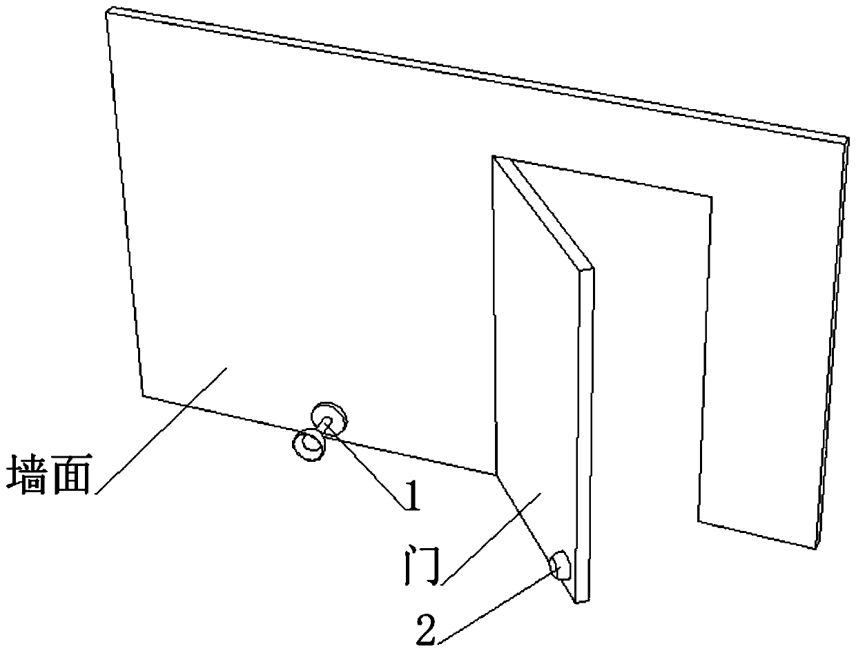
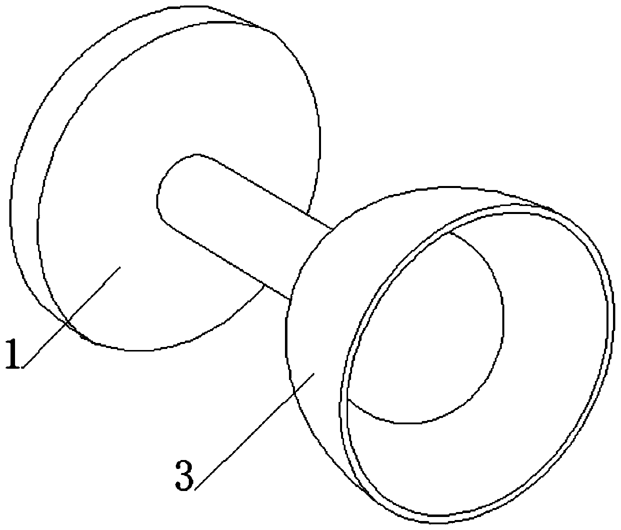
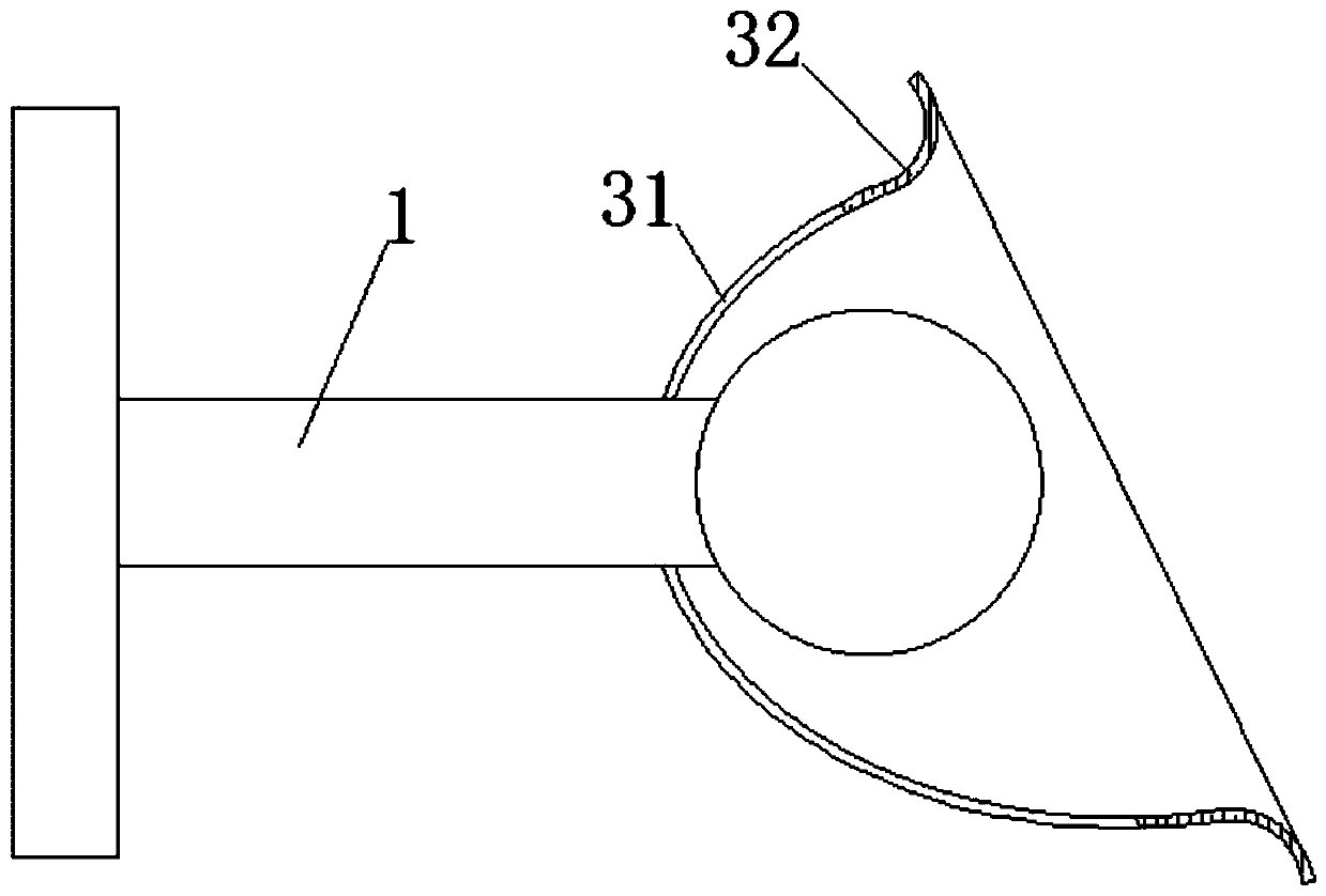
[0045] see Figure 1-3 , a layered pre-drop force door stopper, including a retractable suction head 1 installed on the wall and a built-in base 2 installed on the back of the door, the retracted suction head 1 and the built-in base 2 are matched, and the retracted The outer end of the suction head 1 is fixedly connected with an extension cover 3, the extension cover 3 includes a hard support section 31 and a flange section 32, the hard support section 31 is fixedly connected with the flange section 32, and the hard support section 31 is fixedly connected with the retractable suction head 1 .

[0046] see Figure 5-6 , the inside of the flanging section 32 is excavated with a buffer cavity 4, and the opposite inner walls of the buffer cavity 4 are fixedly connected with a plurality of fixed-point reinforcement blocks 5, and a buffer gap is formed between the ends of the relative multiple fixed-point reinforcement blocks 5 that are close to each other. , it can effectively re...


PUM


Abstract

The invention discloses a layering pre-force-falling type door stop, and belongs to the field of door stops. According to the layering pre-force-falling type door stop, through the arrangement of an extension cover, during door opening, through deformation during deformation outer overturning of the extension cover, the pre-force-falling function is achieved before an inner contraction suction head makes contact with an embedded base on the outer layer, and after the inner contraction suction head and the embedded base are in contact, a sand deformation bag is gradually arranged towards the outer side of the contact point under the action of the inner contraction suction head, and the function of buffering and force unloading is achieved on the inner layer at the time; during door closing,through the sand deformation bag, compared with the prior art, instant acting force generated when the inner contraction suction head and the embedded base are suddenly separated is effectively relieved, accordingly, the integral usage time number and service life of the inner contraction suction head and the embedded base are effectively prevented from being influenced by single-time excessive stress, meanwhile, the situation that the inner contraction suction head falls due to multi-time stress is effectively avoided, and the maintenance cost is reduced.

Description

technical field [0001] The invention relates to the field of door stoppers, more specifically, to a layered pre-drop force type door stopper. Background technique [0002] The door stopper is also commonly known as the door touch, and it is also a device that absorbs and positions the door leaf after it is opened, so as to prevent the wind from blowing or touching the door leaf and closing it. Door stoppers are divided into two types: permanent magnet stoppers and electromagnetic door stoppers. Permanent magnet stoppers are generally used in ordinary doors and can only be controlled manually; electromagnetic door stoppers are used in electrically controlled door and window equipment such as fire doors, which have both manual control and automatic control. control function. [0003] Ordinary permanent magnetic door stoppers are divided into wall-mounted and floor-mounted types according to the installation form, and plastic type and metal type according to the material; elec...

Claims


Application Information

Patent Timeline
Patent Type & Authority Applications(China)
IPC IPC(8): E05C17/46
CPCE05C17/46
Inventor 陈式均
Owner 颜锦程
Why Eureka
Try Eureka