
Circulating evaporator

A technology of evaporator and evaporating tube, applied in forced circulation evaporator, vertical tube evaporator, evaporator accessories, etc., can solve the problems of small contact area of ​​hot steam, reduced evaporation effect, low working efficiency, etc., and achieve high working efficiency , the effect of increasing the response time and improving the work efficiency

Inactive Publication Date: 2019-12-13
安徽鸿昌糖业科技有限公司
View PDF5 Cites 0 Cited by
  • Summary
  • Abstract
  • Description
  • Claims
  • Application Information

AI Technical Summary

Problems solved by technology

The heating chamber provides the heat required for evaporation to the liquid, which promotes the boiling and vaporization of the liquid; the evaporation chamber completely separates the vapor and liquid, and after the heating chamber injects the hot steam into the separator, it is easy to have insufficient temperature after long-term use, and the evaporation effect is reduced. The evaporating tube in the evaporator is cylindrical, which results in a small contact area with the external hot steam and low working efficiency. Therefore, a circulating evaporator that can solve the above problems is urgently needed

Method used


Image

  • Circulating evaporator
  • Circulating evaporator
  • Circulating evaporator

Examples


Embodiment Construction

[0027] The following will clearly and completely describe the technical solutions in the embodiments of the present invention with reference to the accompanying drawings in the embodiments of the present invention. Obviously, the described embodiments are only some, not all, embodiments of the present invention. Based on the embodiments of the present invention, all other embodiments obtained by persons of ordinary skill in the art without making creative efforts belong to the protection scope of the present invention.

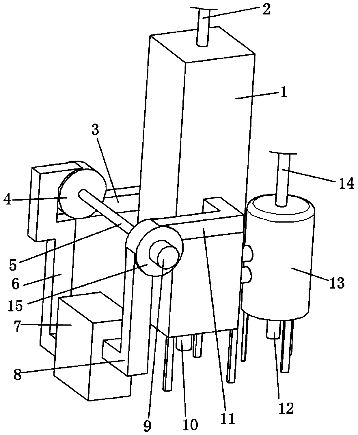
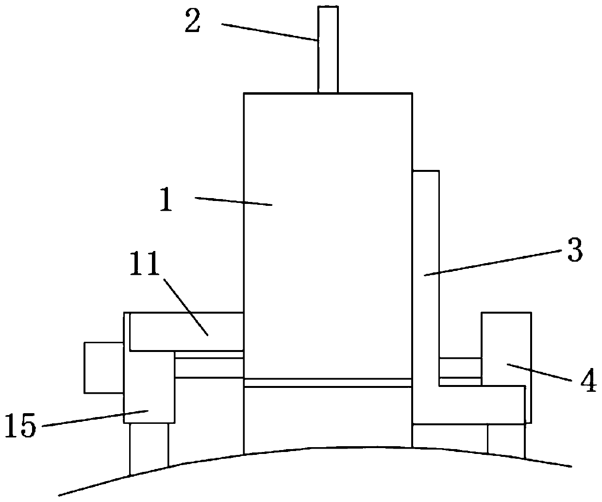
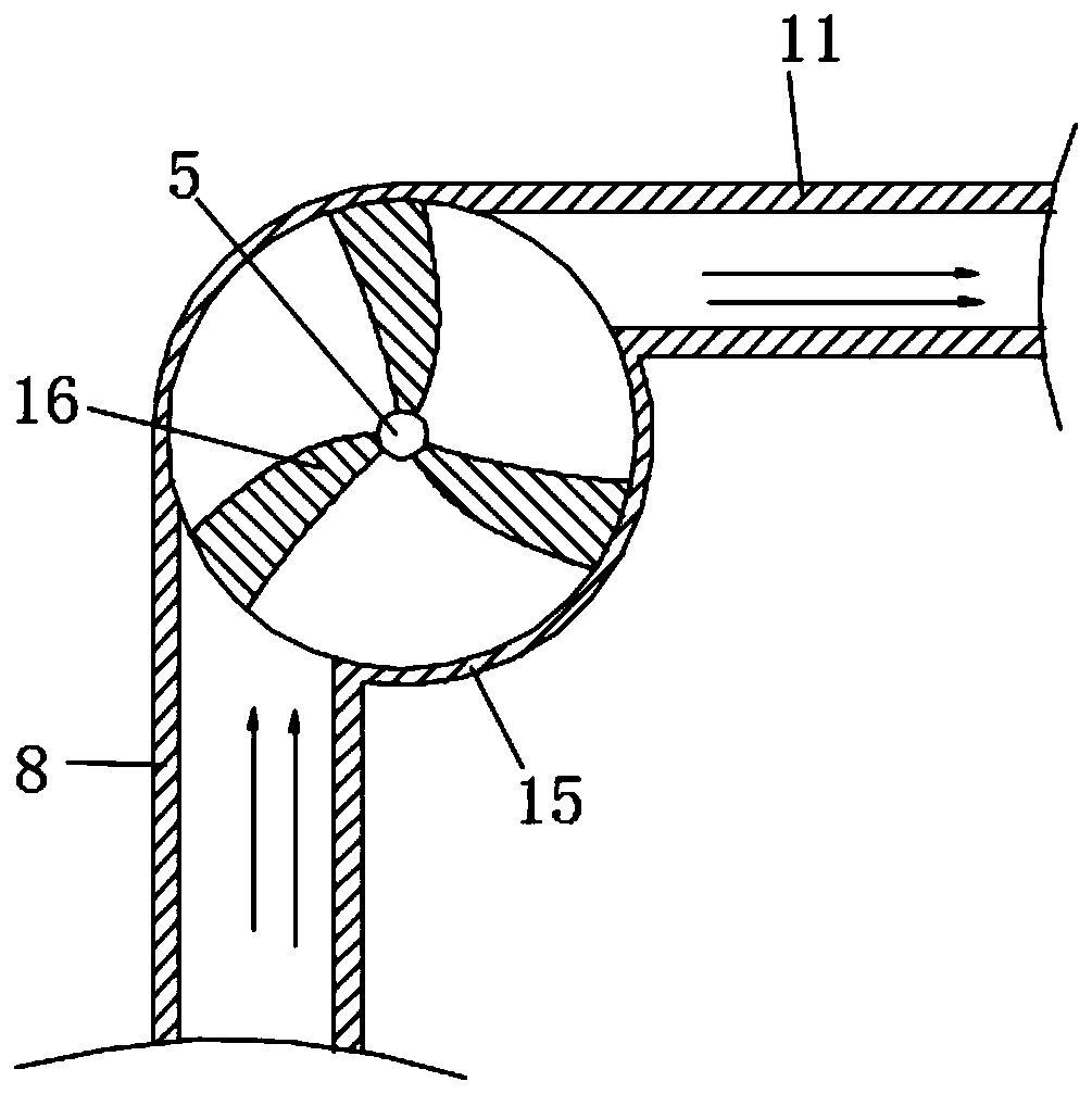
[0028] Such as Figure 1 to Figure 9 As shown, a circulating evaporator includes a separator 1 with a cavity inside and a heating box 7 and an isolation tank 13 respectively arranged on both sides of the separator 1. The heating box 7 is placed outside to realize a simple heating process and low manufacturing cost. The upper and lower ends of the inner cavity of the separator 1 are respectively a superheating chamber 23 and a steam chamber 17. The material flo...


PUM


Abstract

The invention discloses a circulating evaporator. The circulating evaporator comprises a separator having a cavity inside, and further comprises a heating box and an isolation tank respectively arranged on the two sides of the separator, wherein an overheating cavity and a steam cavity are respectively formed in the upper end and the lower end of the inner cavity of the separator; the upper end ofthe overheating cavity is a feeding port; the lower end of the steam cavity is a first discharging port; the heating box is connected with two sides of the overheating cavity through an air inlet device and an air outlet device respectively; the steam cavity is communicated with the inner cavity of the isolation tank through a ventilation pipe; and a ventilation outlet and a second discharging port are formed in the upper end and the lower end of the isolation tank respectively. According to the device, the circulation speed of hot steam between the separator and the heating box can be increased, and working efficiency is improved; a contact area can be increased and reaction time is prolonged; the steam cavity and the isolation tank can achieve a cooling function, generated steam, cooling water and non-condensable steam are discharged separately, and working efficiency is high.

Description

technical field [0001] The invention belongs to the technical field of evaporators, in particular to a circulating evaporator. Background technique [0002] The evaporator is mainly composed of two parts: a heating chamber and an evaporation chamber. The heating chamber provides the heat required for evaporation to the liquid, which promotes the boiling and vaporization of the liquid; the evaporation chamber completely separates the vapor and liquid, and after the heating chamber injects the hot steam into the separator, it is easy to have insufficient temperature after long-term use, and the evaporation effect is reduced. The evaporating tube in the evaporator is cylindrical, which results in a small contact area with the external hot steam and low working efficiency. Therefore, a circulating evaporator that can solve the above problems is urgently needed. Contents of the invention [0003] In view of the above-mentioned problems in the prior art, the present invention p...

Claims


Application Information

Patent Timeline
IPC IPC(8): B01D1/00B01D1/06B01D1/12B01D1/30
CPCB01D1/0094B01D1/06B01D1/12B01D1/30B01D1/305
Inventor 周大钊
Owner 安徽鸿昌糖业科技有限公司
Learn More