
A maximum efficiency tracking dc-dc converter applied to inductive power transmission system and its control method

An inductive power transmission, DC-DC technology, applied in the output power conversion device, the conversion of DC power input to DC power output, the conversion of AC power input to DC power output, etc., can solve the problem of limited adjustable range of equivalent impedance, Unable to achieve dynamic tracking, inapplicability and other problems, achieve high power levels, reduce voltage and current stress, and improve applicability

Active Publication Date: 2021-07-16
HARBIN ENG UNIV
View PDF6 Cites 0 Cited by
  • Summary
  • Abstract
  • Description
  • Claims
  • Application Information

AI Technical Summary

Problems solved by technology

Passive impedance matching is to use the inductor-capacitor impedance adjustment network to achieve the equivalent of a fixed load point, and dynamic tracking cannot be achieved
Active impedance matching means that when working at a fixed frequency, the Buck converter is used to adjust the equivalent load to ensure that the system operates at the maximum efficiency operating point. However, due to its own structural limitations, the adjustable range of the equivalent impedance on the load side is very large. Limited, not suitable for large load changes

Method used


Image

  • A maximum efficiency tracking dc-dc converter applied to inductive power transmission system and its control method
  • A maximum efficiency tracking dc-dc converter applied to inductive power transmission system and its control method
  • A maximum efficiency tracking dc-dc converter applied to inductive power transmission system and its control method

Examples


Embodiment Construction

[0027] Further describe the present invention below in conjunction with accompanying drawing:

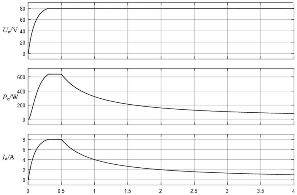
[0028] Such as figure 1 , a maximum efficiency tracking DC-DC converter and its control technology applied in the inductive power transfer system. The main circuit topology is the main circuit of inductive power transfer and the main circuit of impedance matching. The former is mainly composed of loosely coupled transformers and L 1 、C 1 、C s and the coupler self-inductance L p , L s The LCL-S compensation topology composed of the switching tube Q 1 -Q 4 A full-bridge inverter circuit composed of a diode D 1 -D 4 The uncontrolled rectifier bridge and filter capacitor C f composition. Among them, the inverter circuit switch tube Q 1 and Q 2 , Q 3 , Q 4 Both are 180° complementary conduction, the duty cycle is fixed at 0.5, and the switching tube Q 1 and Q 2 Composed of the leading arm LegA and composed of Q 3 , Q 4 The phase angle between the formed lagging bridge ar...


PUM


Abstract

The invention belongs to the field of electric energy transmission, and discloses a maximum efficiency tracking DC-DC converter and its control method for inductive electric energy transmission systems, including LCL-S compensation topology, uncontrolled rectifier bridge and double-tube Buck-Boost circuit; LCL The output of the ‑S compensation topology is connected to the input of the uncontrolled rectifier bridge, and the output of the uncontrolled rectifier bridge is connected to the input of the dual-tube Buck‑Boost circuit. The present invention realizes the constant voltage control of induction electric energy transmission by adjusting the phase shift angle between the leading and lagging bridge arms of the full-bridge inverter circuit, and realizes impedance matching by controlling the DSBB switch tube by adopting an interleaved duty cycle bias modulation strategy. Keep the equivalent load on the output side of the rectifier bridge always at the maximum efficiency load point; the double-tube structure of the present invention can effectively reduce the voltage and current stress of the switch tube, so that the system output has a wider voltage range and a higher power level; The adjustment of the pressure mode can make the load adjustable range wider when the system realizes the maximum efficiency tracking, which greatly improves the applicability of the system.

Description

technical field [0001] The invention belongs to the field of electric energy transmission, and in particular relates to a maximum efficiency tracking DC-DC converter applied to an inductive electric energy transmission system and a control method thereof. Background technique [0002] Traditional power transmission methods such as sockets have the characteristics of hot plugging, which are prone to safety hazards such as electric sparks. Electrical isolation cannot be achieved, and maintenance costs are high. It is difficult to meet the needs of application scenarios such as electric vehicles, mine power supply, and underwater charging. Therefore, It is necessary to realize efficient inductive power transfer. How to improve the efficiency in the process of power transmission, reduce the transmission loss, and save the use cost is particularly important. [0003] According to the different forms of relay energy in the energy transmission process, wireless energy transmission...

Claims


Application Information

Patent Timeline
Patent Type & Authority Patents(China)
IPC IPC(8): H02M3/335H02M7/5387H02M3/158H02J50/10
CPCH02M3/1582H02M3/1584H02M3/33553H02M7/53871H02J50/10H02M3/1586
Inventor 游江程连斌张镠钟彭辉李晓旭周玮王西贝
Owner HARBIN ENG UNIV
Learn More