
Dragging experiment table for small light-load motor

A light-load, test bench technology, applied in the field of drag test benches, can solve problems such as weak protection, no protective structure, and large safety hazards, and achieve the effect of enhancing stability

Inactive Publication Date: 2019-12-10
杨国丽
View PDF8 Cites 0 Cited by
  • Summary
  • Abstract
  • Description
  • Claims
  • Application Information

AI Technical Summary

Problems solved by technology

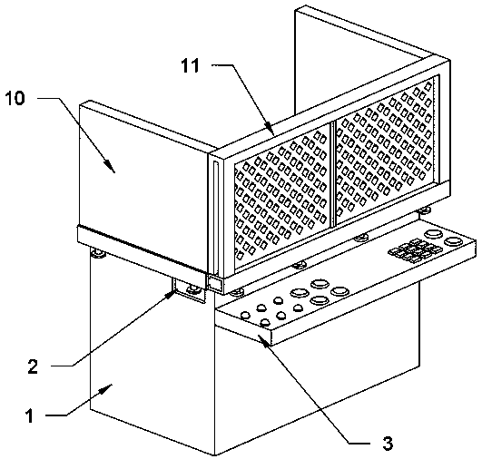
[0007] In order to solve the above-mentioned technical problems, the present invention provides a drag test bench for small light-loaded motors to solve the existing problem that the protection is weak, and some abnormal faults and phenomena are often prone to occur during detection experiments. The above-mentioned device is not equipped with a corresponding protective structure, and the safety hazard is relatively large; moreover, the structural flexibility is poor, the overall structure of the above-mentioned device is rigid, and it cannot be combined with the workbench to create different working environments.

Method used


Image

  • Dragging experiment table for small light-load motor
  • Dragging experiment table for small light-load motor
  • Dragging experiment table for small light-load motor

Examples


Embodiment Construction

[0031] Embodiments of the present invention will be further described in detail below in conjunction with the accompanying drawings and examples. The following examples are used to illustrate the present invention, but should not be used to limit the scope of the present invention.

[0032] as attached figure 1 to attach Figure 8 Shown:

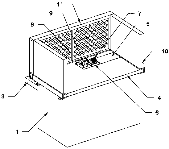
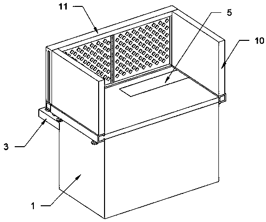
[0033] The invention provides a drag test bench for small light-load motors, including a cabinet body 1, a rectangular hole 2, a console 3, a test bench table 4, a sliding groove 401, a card slot A402, a card slot B403, and a fixed plate for an experiment body 5. Card slot C501, motor fixing seat 6, sliding seat A601, sliding block A602, motor 7, gear A701, test structure fixing seat 8, sliding seat B801, sliding block B802, test structure 9, gear B901, gear C902, gear D903, side protection plate 10, main protection plate 11, frame 1101, door panel 1102 and rectangular magnet 1103; the cabinet body 1 is a rectangular cabinet-shaped struct...


PUM


Abstract

The invention provides a dragging experiment table for a small light-load motor. The dragging experiment table comprises a cabinet body, a door plate and a rectangular magnet, the cabinet body is of arectangular cabinet-shaped structure, a rectangular hole is formed in the left end face of the cabinet body, and an experiment table plate is welded to the top end face of the cabinet body. The sliding block B is rotatably connected with a test structure, and the outer wall of the test structure is fixedly connected with a gear B, a gear C and a gear D in sequence from left to right. The experiment main body fixing plate and the sliding groove are connected in a sliding and inserting manner; so that under the non-experimental state, the experiment main body fixing plate can be inserted into the sliding groove in a horizontal overturning manner; at this time, the whole experiment table plate is in a plane state and can be used for other operations; and when the experiment main body fixingplate is inserted into the sliding groove, the clamping groove C is aligned with the clamping groove B, so that the installation of the side protection plate is not influenced during use, and comparedwith an existing device, the device is more reasonable in structure and can create different use environments through switching.

Description

technical field [0001] The invention belongs to the technical field of motor test benches, and more specifically relates to a drag test bench for small light-load motors. Background technique [0002] The generator is represented by the letter G in the circuit. Its main function is to convert mechanical energy into electrical energy. At present, the most commonly used method is to use thermal energy, water energy, etc. to drive the rotor of the generator to generate electricity. Before the motor is assembled, it needs to perform performance speed detection under different gear ratio conditions. [0003] Such as the application number: CN201210001570.3, the present invention relates to a permanent magnet generator performance testing universal test bench, including a frame, a lifting mechanism is provided on the frame, the lifting mechanism includes a lifting platform, and a motor and a motor are installed on the lifting platform. A disc coupler connected to the output shaft...

Claims


Application Information

Patent Timeline
Patent Type & Authority Applications(China)
IPC IPC(8): G01R31/34G01R1/02B01L9/02
CPCB01L9/02G01R1/02G01R31/34
Inventor 杨国丽
Owner 杨国丽
Learn More