Tube bundle heat exchanger

A technology of tube bundle heat exchanger and heat exchange tube, which is applied in the direction of heat exchanger type, indirect heat exchanger, heat exchange equipment, etc. flow loss, etc.

Active Publication Date: 2019-12-10
BEIHANG UNIV
View PDF5 Cites 8 Cited by
  • Summary
  • Abstract
  • Description
  • Claims
  • Application Information

AI Technical Summary

Problems solved by technology

Although the above-mentioned tube-bundle heat exchanger has high heat exchange efficiency and large heat transfer per unit weight, the heat exchange medium (such as air flow) outside the heat exchanger needs to change the flow direction, and the heat exchange medium turns back and forth to the outside. The heat exchange medium brings a lot of flow loss
Take the tube-bundle heat exchanger applied to the engine of the aircraft as an example. This energy loss has a serious impact on the thermal efficiency and work of the engine, and may even cause the hypersonic aircraft to fail to complete the take-off process and reach the cruising state.

Method used


Image

  • Tube bundle heat exchanger
  • Tube bundle heat exchanger
  • Tube bundle heat exchanger

Examples


Embodiment Construction

[0022] In order to enable those skilled in the art to better understand the technical solutions of the present invention, the present invention will be further described in detail below in conjunction with the accompanying drawings and specific embodiments.

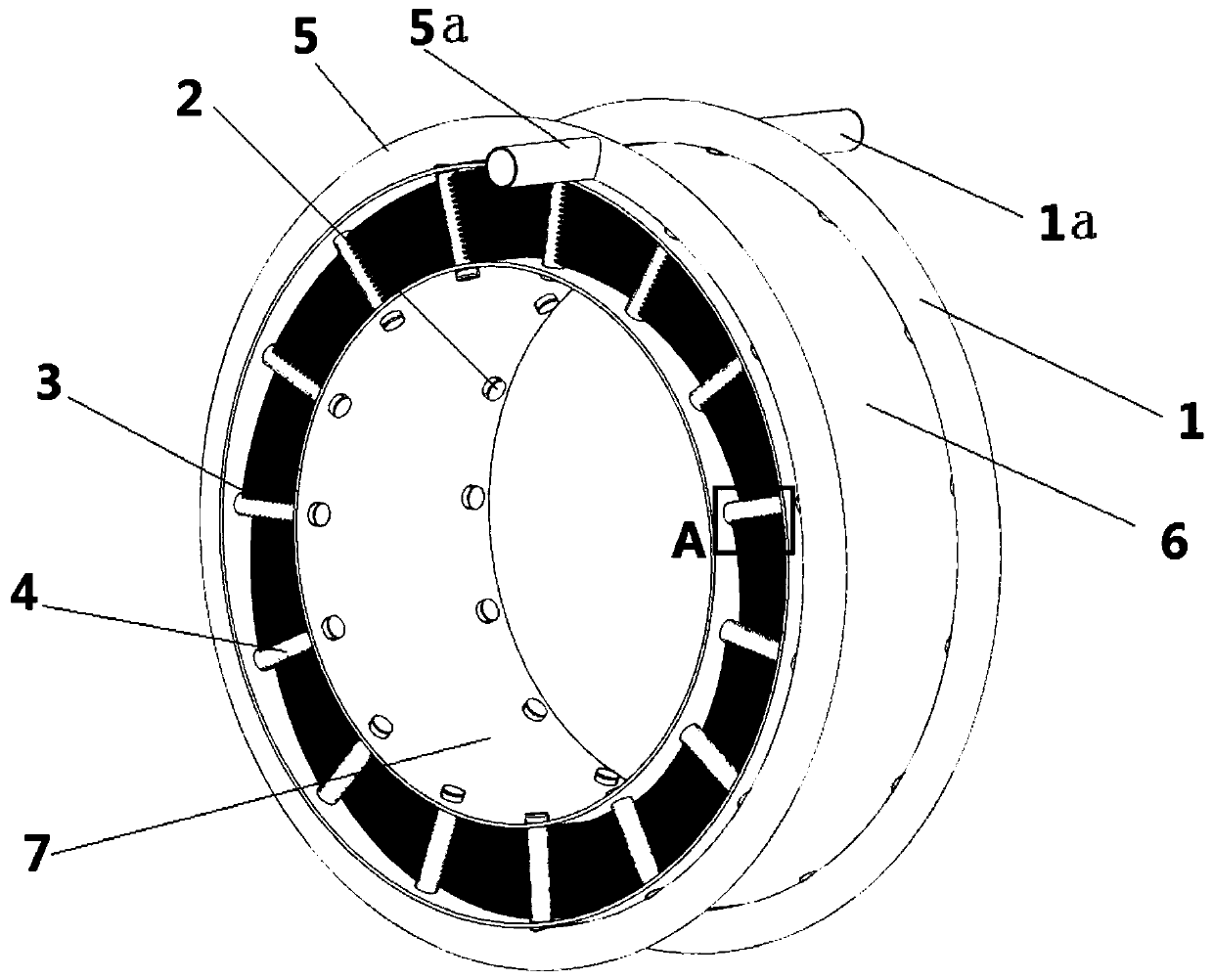
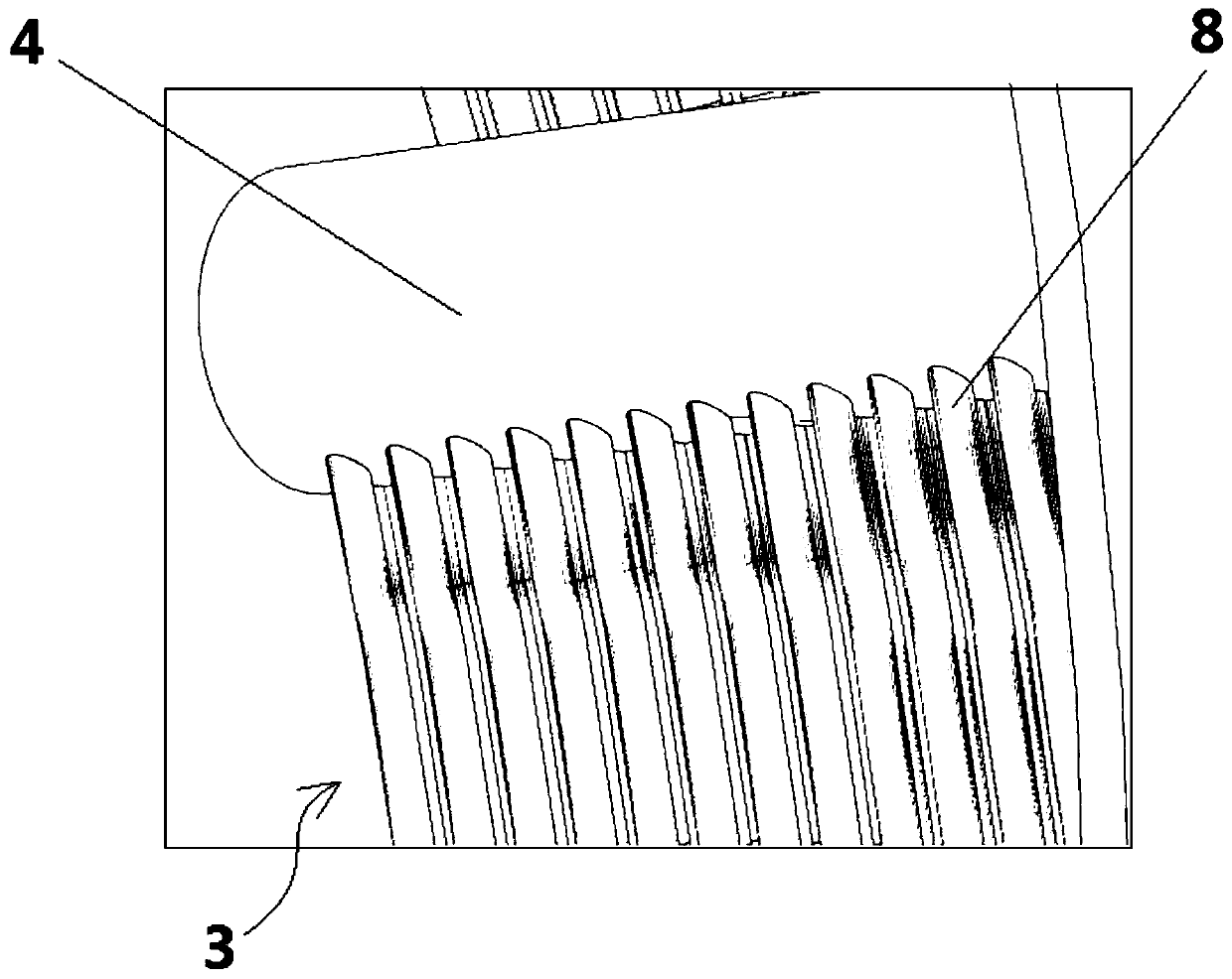
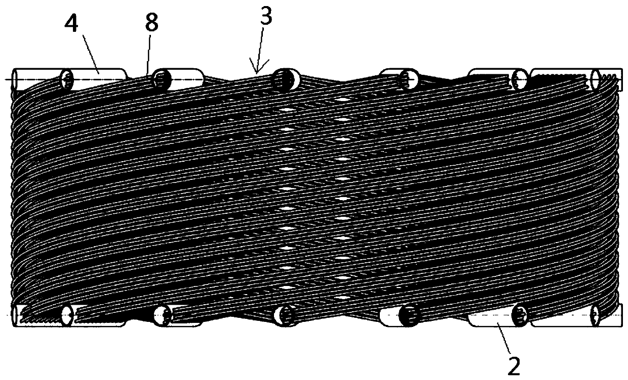
[0023] Please refer to figure 1 , figure 1 It is a structural schematic diagram of a specific embodiment of the tube-bundle heat exchanger provided by the present invention; figure 2 for figure 1 Partial enlarged schematic diagram of part A in the middle; image 3 for figure 1 Schematic diagram of multiple heat exchange tube banks in ; Figure 4 for image 3 Schematic diagram of a single row of heat exchange tubes in .

[0024] The tube bundle heat exchanger provided in this embodiment includes a shell forming an annular cavity, such as figure 1 As shown, the housing includes an outer shell 6 and an inner shell 7, the inner shell 7 is nested in the outer shell 6, and an annular cavity is formed between them. Spec...


PUM


Abstract

The invention discloses a tube bundle heat exchanger comprising a shell forming an annular cavity, wherein a plurality of heat exchange tube rows are arranged in the annular cavity, each of the heat exchange tube rows helically extends along the axial direction of the annular cavity, and the plurality of heat exchange tube rows are staggered in the circumferential direction of the annular cavity.The tube bundle heat exchanger provided by the solution has the advantages of compact structure, light weight and strong heat exchange capacity. It is particularly important that, under the premise ofobtaining the required heat exchange efficiency in the tube bundle heat exchanger, the external heat exchange medium does not need to change the flow direction, that is, enters in the axial direction, and continues to flow in the axial direction inside the annular cavity and finally flows out, thereby avoiding the back and forth turning of the airflow to reduce the flow energy loss of the external heat exchange medium. The tube bundle heat exchanger can also withstand high temperatures and pressures, and can work reliably under conditions that require super heat exchange capacity and in harshworking conditions.

Description

technical field [0001] The invention relates to the technical field of heat exchangers, in particular to a tube bundle heat exchanger. Background technique [0002] As a device for energy exchange, heat exchangers are widely used in various fields such as energy, chemical industry, electronics, aerospace and so on. With the development of technology in various fields, the requirements for the comprehensive performance of heat exchangers are also constantly improving. [0003] Existing heat exchangers have their own characteristics. For example, microchannel heat exchangers used in electronic equipment are compact in structure and light in weight, but they cannot work in high-temperature and high-pressure environments; shell-and-tube heat exchangers used in chemical equipment The heat exchanger can withstand high temperature and high pressure, but it is large in size and heavy in weight. The heat exchange rate per unit weight of the heat exchanger only reaches the level of 2...

Claims


Application Information

Patent Timeline
Patent Type & Authority Applications(China)
IPC IPC(8): F28D7/02F28F21/08
CPCF28D7/024F28F21/087
Inventor 邹正平付超王一帆
Owner BEIHANG UNIV
Why Eureka
Try Eureka