
Cooling structure of cylinder cover of diaphragm compressor

A diaphragm compressor and cooling structure technology, applied in the field of compressors, can solve problems such as loosening of pressure valve cover and exhaust flange bolts, increase of air separation pressure and saturated vapor pressure, and large pressure ratio of diaphragm compressors. The effect of lowering the cylinder head temperature, lowering the exhaust temperature, and increasing the heat exchange area

Inactive Publication Date: 2019-12-10
XI AN JIAOTONG UNIV
View PDF8 Cites 1 Cited by
  • Summary
  • Abstract
  • Description
  • Claims
  • Application Information

AI Technical Summary

Problems solved by technology

[0003] Because the pressure ratio of the diaphragm compressor is generally large, especially the cylinder head of the high-pressure diaphragm compressor is relatively thick, the high-pressure ratio leads to high exhaust temperature, and the cylinder head is thick, it is difficult to transfer the heat through the surface of the cylinder head The compression heat is exported within the
Therefore, the overall temperature of the cylinder head is high, so that the thermal stress of the cylinder head cannot be ignored, resulting in the loosening of the pressure valve cover and exhaust flange bolts, endangering the safety of the system operation
Diaphragm compressor has a high temperature in the diaphragm cavity, and the temperature of the hydraulic oil will increase through the heat conduction of the diaphragm. If the hydraulic oil temperature is too high, the aging will be accelerated. After the hydraulic oil is polluted, the lubrication conditions of the moving parts will become worse and the acceleration will be accelerated. Wear of moving parts
An increase in the temperature of the hydraulic oil will also lead to an increase in the air separation pressure and saturated vapor pressure in the hydraulic oil, making cavitation more likely to occur, resulting in pressure fluctuations in the hydraulic system
[0004] The high-temperature area of ​​the diaphragm compressor is mainly concentrated near the exhaust valve in the central area, and there is always high-temperature exhaust air passing through, and the heat flux density is also relatively high. Most of the existing cooling solutions are to build cooling water channels inside the cylinder head, pass water or The oil is cooled, and the cylinder head is cooled by face-to-face heat exchange between the cooling water and the water channel wall inside the cylinder head. However, the traditional way of water channeling is mostly to drill holes from the side wall of the cylinder head to the inside of the cylinder head. The contact area between the water channel and the middle high temperature area Very small, the heat exported by the cooling water is very small, and the large amount of heat in the central high temperature area cannot be taken away in time, the temperature near the exhaust valve is still high, and the cooling effect is not obvious

Method used


Image

  • Cooling structure of cylinder cover of diaphragm compressor
  • Cooling structure of cylinder cover of diaphragm compressor
  • Cooling structure of cylinder cover of diaphragm compressor

Examples


Embodiment Construction

[0030] Hereinafter, specific embodiments of the application will be described in detail with reference to the accompanying drawings. According to these detailed descriptions, those skilled in the art can clearly understand the application and can implement the application. Without violating the principle of the present application, the features in various embodiments can be combined to obtain new implementations, or to replace some features in some embodiments to obtain other preferred implementations.

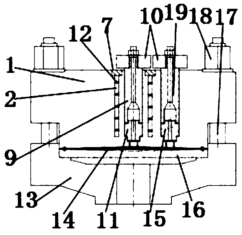
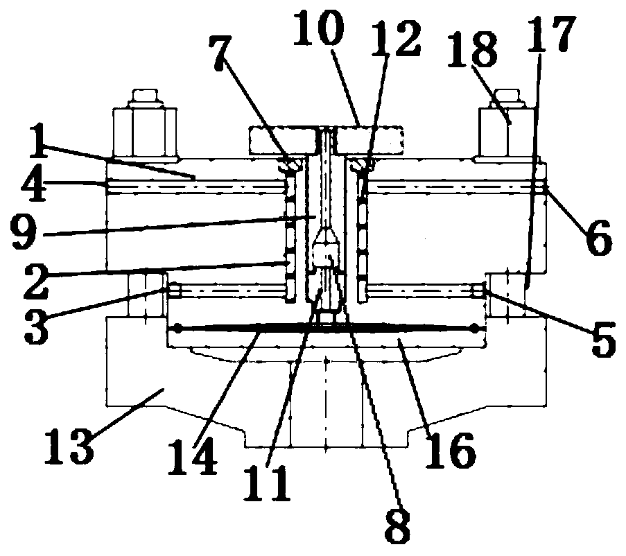
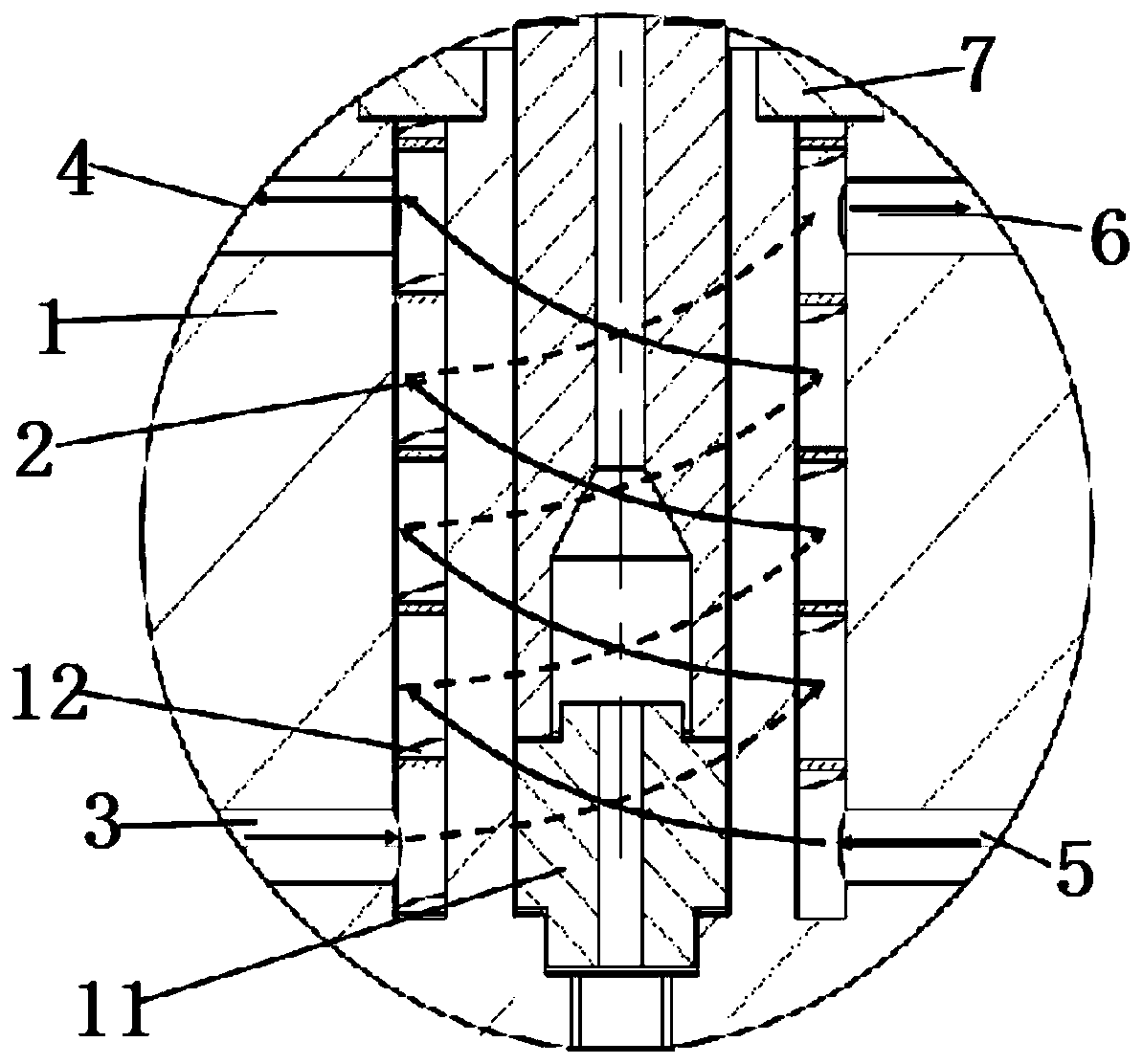
[0031] See Figure 1~4 , The present application provides a diaphragm compressor cylinder head cooling structure, including a cylinder head 1, a cooling water tank 2 is provided on an end surface of the cylinder head 1, the cooling water tank 2 is provided inside the cylinder head 1, the cylinder head 1 is provided with an exhaust assembly on the end surface, the cooling water tank 2 surrounds the exhaust assembly, the cooling water tank 2 communicates with the water inlet group,...


PUM


Abstract

The invention relates to a cooling structure of a cylinder cover of a diaphragm compressor. According to most traditional water channel perforating manners, perforation is performed in the direction facing the insides of cylinder covers from the side walls of the cylinder covers, the heat exchange areas, passing central high-temperature zones, of water channels are very small, a lot of heat of thecentral high-temperature zones cannot be brought away timely, and the cooling effect is not obvious. The cooling structure of the cylinder cover of the diaphragm compressor comprises the cylinder cover; a cooling water groove is formed in the end surface of the cylinder cover and is formed inside the cylinder cover; an exhaust component is arranged on the cylinder cover; the cooling water groovesurrounds the exhaust component, communicates with a water inlet group and communicates with a water outlet group; the water inlet group is formed in the side surface of the cylinder cover; the wateroutlet group is formed in the side surface of the cylinder cover; a spiral ring is arranged in the water groove, so that cooling water flows sufficiently in the water groove, and a stagnant water zoneis prevented. The heat exchange area of the cooling water and the central high-temperature zone is increased, the heat of the central high-temperature zone is guided out, and the temperatures of thecylinder cover and exhaust are reduced.

Description

Technical field [0001] The application belongs to the technical field of compressors, and particularly relates to a diaphragm compressor cylinder head cooling structure. Background technique [0002] Diaphragm compressor is a positive displacement compressor. Because of its good sealing performance, wide pressure range, and relatively large compression, it is widely used in hydrogen refueling stations and other petrochemical fields to compress and transport various high-purity gases, Valuable rare gas, toxic and harmful gas and corrosive gas. In a diaphragm compressor, the piston pushes the working oil in the cylinder oil cavity, and then pushes the diaphragm to reciprocate in the diaphragm cavity to change the working volume of the air cavity, and achieve no leakage with the cooperation of the suction and exhaust valves Cyclical work process. [0003] Because the pressure ratio of the diaphragm compressor is generally larger, especially the cylinder head of the high-pressure dia...

Claims


Application Information

Patent Timeline
Patent Type & Authority Applications(China)
IPC IPC(8): F04B39/06F04B39/12
CPCF04B39/06F04B39/125
Inventor 彭学院任省栋汪婷贾晓晗
Owner XI AN JIAOTONG UNIV
Learn More