Hybrid excitation multi-phase reluctance motor and power generation system
A technology of reluctance motor and hybrid excitation, which is applied in the direction of motors, synchronous machines, electromechanical devices, etc., and can solve the problem of narrow magnetic field adjustment range
- Summary
- Abstract
- Description
- Claims
- Application Information
AI Technical Summary
Problems solved by technology
Method used
Image

Examples
Embodiment 1
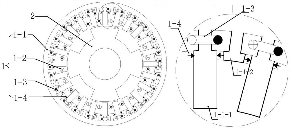
[0125] see figure 1 Describe this embodiment 1. The hybrid excitation polyphase reluctance motor described in this embodiment includes a stator 1 and a rotor 2, which are coaxial and have an air gap, and the rotor 2 is located in the stator 1;
[0126] The rotor 2 is composed of a rotor iron core, which is slotted along the axial direction on the air gap side of the rotor iron core, and the formed teeth and grooves are arranged alternately along the circumferential direction;
[0127] The stator 1 is composed of a stator core 1-1, an m-phase symmetrical armature winding 1-2, an excitation winding and a permanent magnet 1-4; wherein, m is the number of phases of the motor;
[0128] The stator core 1-1 has a cylindrical structure, the air gap side is slotted in the axial direction, and the formed teeth and slots are alternately arranged in turn in the circumferential direction; the air gap side of the stator core 1-1 forms a total of 4Pmk teeth, and 4Pmk teeth are composed of ...
Embodiment 2
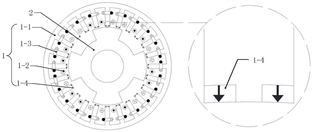
[0137] see figure 1 Describe the second embodiment. The hybrid excitation polyphase reluctance motor described in this embodiment includes a stator 1 and a rotor 2, which are coaxial and have an air gap, and the rotor 2 is located in the stator 1;
[0138] The rotor 2 is composed of a rotor iron core, which is slotted along the axial direction on the air gap side of the rotor iron core, and the formed teeth and grooves are arranged alternately along the circumferential direction;
[0139] The stator 1 is composed of a stator core 1-1, an m-phase symmetrical armature winding 1-2, an excitation winding and a permanent magnet 1-4; wherein, m is the number of phases of the motor;
[0140] The stator core 1-1 is a cylindrical structure, and the air gap side is slotted along the axial direction, and the formed teeth and slots are alternately arranged in the circumferential direction;
[0141] A total of 2Pmk teeth are formed on the air gap side of the stator core 1-1, each tooth i...
Embodiment 3
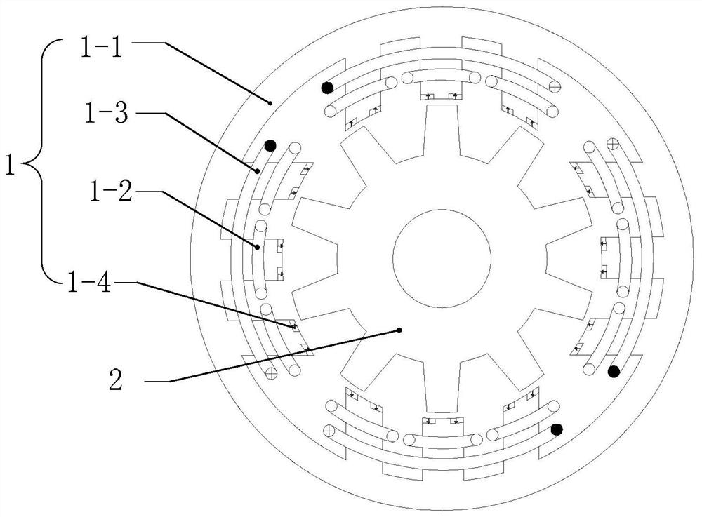
[0151] see image 3 and Figure 4 Describe the third embodiment. The hybrid excitation polyphase reluctance motor described in this embodiment includes a stator 1 and a rotor 2, which are coaxial and have an air gap, and the rotor 2 is located in the stator 1;
[0152] The rotor 2 is composed of a rotor iron core, which is slotted along the axial direction on the air gap side of the rotor iron core, and the formed teeth and slots are alternately arranged along the circumferential direction;
[0153] The stator 1 is composed of a stator core 1-1, an m-phase symmetrical armature winding 1-2, an excitation winding and a permanent magnet 1-4; wherein, m is the number of phases of the motor;
[0154] The stator core 1-1 is a cylindrical structure, and the air gap side is slotted along the axial direction, and the formed teeth and slots are alternately arranged in the circumferential direction;
[0155] A total of 2Pmk teeth are formed on the air gap side of the stator core 1-1, a...
PUM
 Abstract
Description
Claims
Application Information
 - R&D
- Intellectual Property
- Life Sciences
- Materials
- Tech Scout
- Unparalleled Data Quality
- Higher Quality Content
- 60% Fewer Hallucinations
Browse by: Latest US Patents, China's latest patents, Technical Efficacy Thesaurus, Application Domain, Technology Topic, Popular Technical Reports.
© 2025 PatSnap. All rights reserved.Legal|Privacy policy|Modern Slavery Act Transparency Statement|Sitemap|About US| Contact US: help@patsnap.com