Hydraulic control system
A technology of hydraulic control system and control valve, applied in the direction of fluid pressure actuation device, earth mover/shovel, servo motor, etc. The effect of high fuel consumption, high utilization rate and improving the efficiency of operating machinery
- Summary
- Abstract
- Description
- Claims
- Application Information
AI Technical Summary
Problems solved by technology
Method used
Image

Examples
Embodiment 1
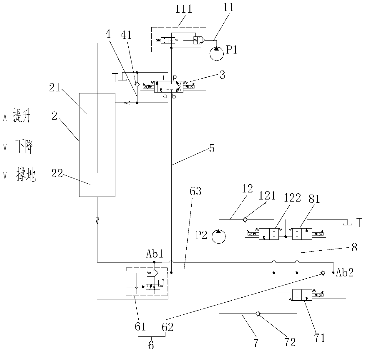
[0038] Such as figure 1 As shown, this embodiment provides a hydraulic control system for driving a working device to work. The hydraulic control system includes at least one hydraulic pump and an actuator 2. At least one hydraulic pump discharges working oil, and the actuator 2 works by being supplied with working oil from the above-mentioned at least one hydraulic pump. The actuator 2 can be a hydraulic cylinder, which has two chambers, namely a rod chamber 21 and a rodless chamber 22 .
[0039] There are two hydraulic pumps, namely hydraulic pump IP1 and hydraulic pump IIP2. Under the control of control valve I3, hydraulic pump IP1 can supply oil to the two cavities of actuator 2 respectively. During the lifting process of the working device, hydraulic pump IIP2 It can be combined with the hydraulic pump IP1 to supply oil to the actuator 2. In this embodiment, the hydraulic pump IIP2 can flow together with the hydraulic pump IP1 to supply oil to the rodless chamber 22 of ...
Embodiment 2
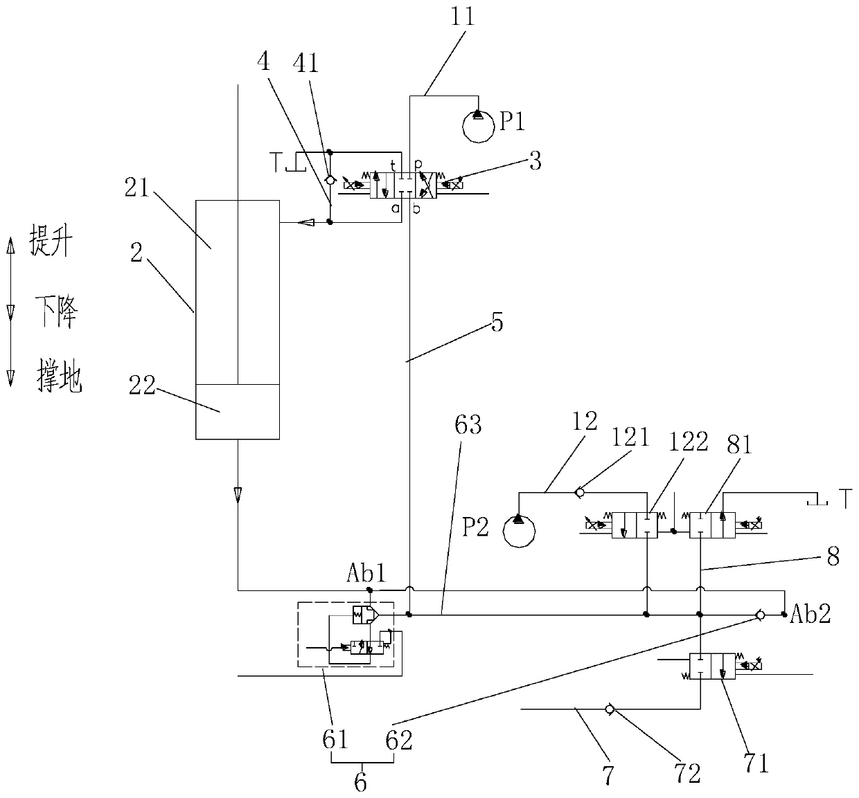
[0056] Such as figure 2 As shown, this embodiment is basically the same as Embodiment 1, the only difference is that the hydraulic control system of this embodiment does not need to set the control valve II111, and the oil supply of the hydraulic pump IP1 can be controlled by the control valve I3. Specifically, When the control valve I3 is in the neutral position, the hydraulic pump IP1 stops supplying oil to the actuator 2, and when the control valve I3 is in the left and right positions, it supplies oil to the two cavities of the actuator 2 respectively.
[0057] In this embodiment, when the working device is descending, the oil drained from the rodless chamber 22 of the actuator 2 can be partially regenerated through the regeneration oil circuit 7, and part of the oil can be returned through the oil return circuit 8. In this embodiment, only through The oil return circuit 8 is used to adjust the descending speed of the working device.
[0058] The control valve I3 in this...
Embodiment 3
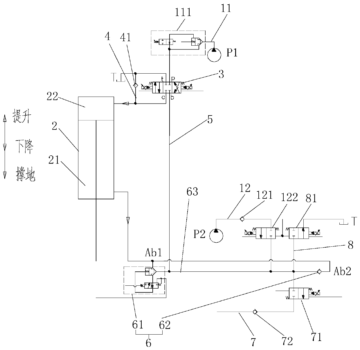
[0060] Such as image 3 As shown, this embodiment is basically the same as the first embodiment, the only difference is that the rod chamber 21 and the rodless chamber 22 of the actuator 2 are set in opposite directions. The working oil port a communicates with the rodless chamber 22 , and the working oil port b communicates with the rod chamber 21 through the working oil passage 5 . When the working device is lifted, the hydraulic pump IP1 and the hydraulic pump IIP2 can merge to supply oil to the rod chamber 21 of the actuator 2, and the merged hydraulic oil passes through the control valve III61 and / or the first one-way valve 62 to supply the actuator 2 When the working device is lowered, the working oil discharged from the rod chamber 21 of the actuator 2 flows out through the control valve III61, and is regenerated through the regeneration oil circuit 7 and / or through the oil return circuit 8 The oil is returned to the oil return tank T and / or the oil is returned to the ...
PUM
 Abstract
Description
Claims
Application Information
 - Generate Ideas
- Intellectual Property
- Life Sciences
- Materials
- Tech Scout
- Unparalleled Data Quality
- Higher Quality Content
- 60% Fewer Hallucinations
Browse by: Latest US Patents, China's latest patents, Technical Efficacy Thesaurus, Application Domain, Technology Topic, Popular Technical Reports.
© 2025 PatSnap. All rights reserved.Legal|Privacy policy|Modern Slavery Act Transparency Statement|Sitemap|About US| Contact US: help@patsnap.com