Combined steam injection device

A combined, steam technology, applied in the field of ejectors, can solve the problems of drastic changes in the ejection performance of the ejector and the inability to achieve the best ejection performance of the ejector, and achieve the effect of avoiding the impact

Pending Publication Date: 2019-12-06
无锡海力自控工程有限公司 +1
View PDF0 Cites 3 Cited by
  • Summary
  • Abstract
  • Description
  • Claims
  • Application Information

AI Technical Summary

Problems solved by technology

[0004] The purpose of the present invention is to provide a combined steam injection device to solve the problem that the existing injector can only achieve the best working condition under the design conditions, and the injection performance of the injector is often caused by the change of gas parameters in actual production. Problems with drastic variations that do not achieve the optimum ejection performance for which the injector is designed

Method used


Image

  • Combined steam injection device
  • Combined steam injection device
  • Combined steam injection device

Examples


Embodiment 1

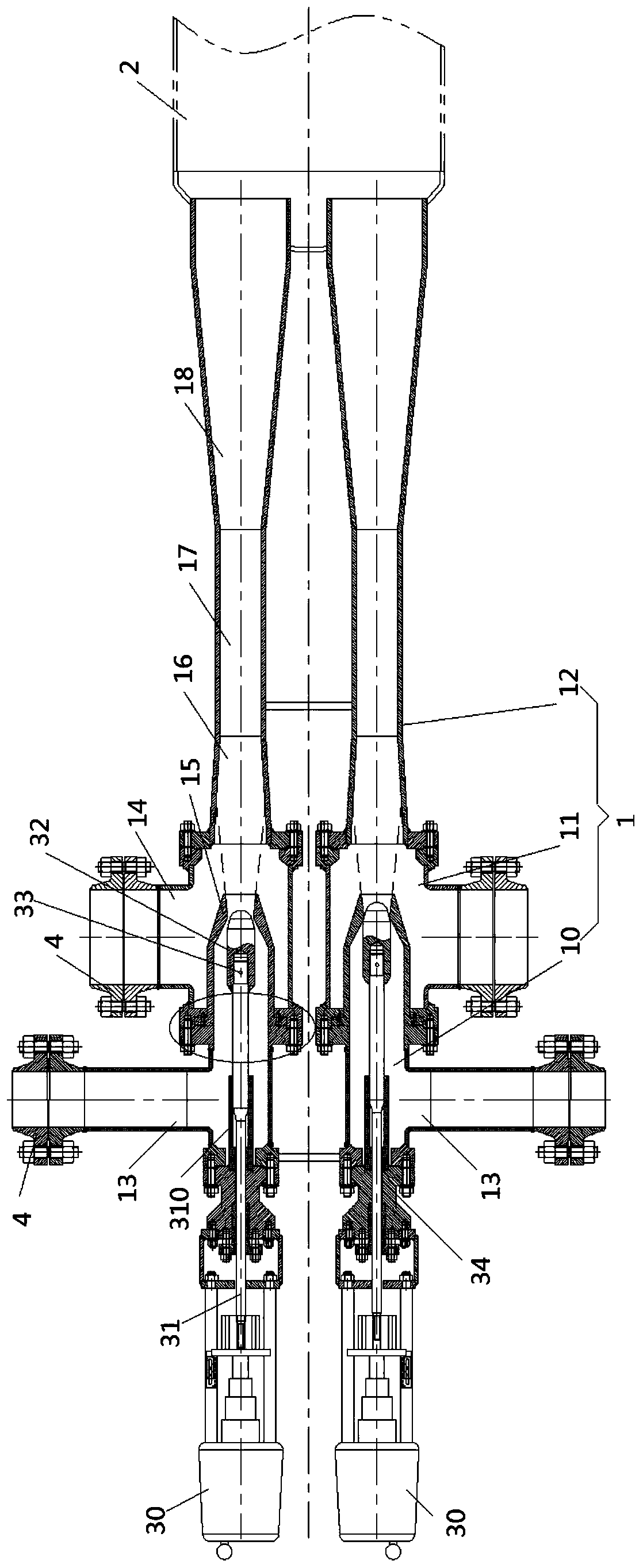
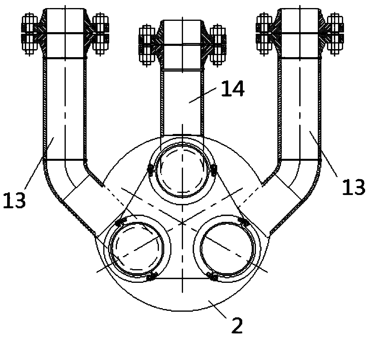
[0022] The invention provides a combined steam injection device, such as figure 1 and image 3 As shown, it includes several ejectors 1 and connecting parts 2 that are independently arranged, wherein, several of the ejectors 1 are sealed and connected with the connecting part 2, and several of the ejectors 1 are provided with There is a throttling mechanism for individually controlling the flow rate of the working fluid in each of the ejectors 1; the ejectors 1 communicate with the external steam pipeline through the connecting part 2. Preferably, there are three ejectors 1 .

[0023] The ejector 1 includes a high-pressure steam chamber 10, a low-pressure steam chamber 11, and a mixed steam chamber 12 that communicate with each other, wherein the side walls of the high-pressure steam chamber 10 and the low-pressure steam chamber 11 are respectively provided with working fluid inlets 13 and ejection fluid inlet 14; one end of the high-pressure steam chamber 10 communicates wi...


PUM


Abstract

The invention discloses a combined steam injection device, and belongs to the technical field of ejector. The combined steam injection device comprises a plurality of ejectors which are independentlyarranged and a connecting part, wherein the plurality of the ejectors are connected with the connecting part in a sealing manner, and the plurality of the ejectors are provided with throttling mechanisms to individually control the flow of a working fluid in each ejector; the ejectors communicate with external steam pipelines through the connecting part. According to the combined steam injection device, throttling mechanisms are arranged on the ejectors to individually control the flow of the working fluid in each ejector. When external gas parameters change, especially when the discharge gasflow changes greatly, the flow of the working fluid in each ejector can be adjusted to enable that the combined steam injection device can achieve the best injection condition and the injection performance required by the combined steam injection device can be met.

Description

technical field [0001] The invention relates to the technical field of ejectors, in particular to a combined steam ejector. Background technique [0002] The working principle of the steam ejector is: the high-pressure steam converts the pressure energy into kinetic energy through the nozzle, and forms a high-speed jet at the outlet of the nozzle, and the pumped fluid is drawn into the suction chamber due to the strong shearing effect between it and the working fluid. The turbulent diffusion effect of the jet boundary layer makes the exchange of mass, momentum and energy between the two fluids, so the velocity of the working fluid decreases continuously, while the velocity of the ejected fluid increases continuously, and a single uniform flow is formed somewhere in the mixing chamber. mixed fluid. The kinetic energy in the diffuser is converted into pressure energy, and the mixed fluid is decelerated and pressurized to a certain back pressure and then discharged out of the ...

Claims


Application Information

Patent Timeline
IPC IPC(8): F04F5/16F04F5/46
CPCF04F5/16F04F5/46F04F5/461F04F5/466
Inventor 陈永彬唐江明小林杨光贤黄旭初向泽岗赵志忠洪晓敏胡俊刚李夕华罗彪杨昌森邓立杨明王宽陆晔杨如贤
Owner 无锡海力自控工程有限公司
Why Eureka
Try Eureka