
High-speed resin coating 3D printing system

A 3D printing and resin technology, applied in the field of 3D printing, can solve the problems of large solid-liquid force, long time, damage to samples, etc., and achieve the effect of increasing the speed of 3D printing

Active Publication Date: 2019-12-06
BMF NANO MATERIAL TECH CO LTD
View PDF18 Cites 7 Cited by
  • Summary
  • Abstract
  • Description
  • Claims
  • Application Information

AI Technical Summary

Problems solved by technology

[0003] In view of the above technical problems, the present invention provides a high-speed resin-coated 3D printing system based on a new film-based coating technology. The shortcoming of slow printing also solves the problem of strong solid-liquid force and damage to the sample when using a transparent hard window

Method used


Image

  • High-speed resin coating 3D printing system
  • High-speed resin coating 3D printing system
  • High-speed resin coating 3D printing system

Examples


Embodiment Construction

[0018] The specific technical solutions of the present invention are described in conjunction with the examples.

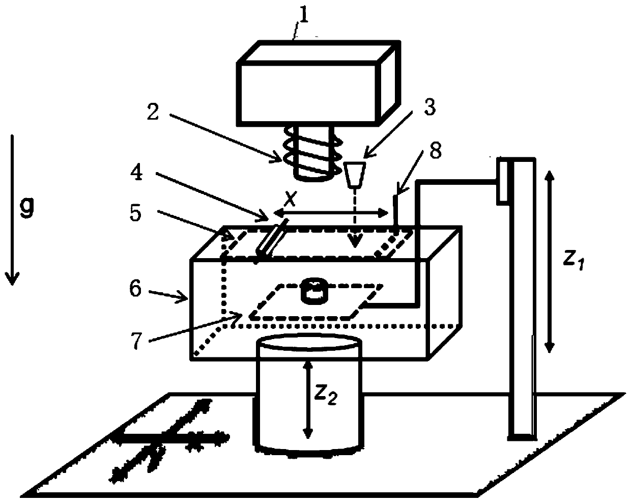
[0019] like figure 1 A high-speed resin-coated 3D printing system shown includes an exposure optical system 1, a film 5, a laser displacement meter 3, a hob 4, a bubble scraper 8, a resin tank 6, and a sample table 7;

[0020] The sample table 7 is connected with the lifting device, the sample table 7 is located in the resin tank 6, and the film 5 is covered on the resin in the resin tank 6; the resin tank 6 is installed on the three-dimensional motion control axis; the exposure optical system 1 is located in the resin tank 6. Above the groove 6, the projection lens of the exposure optical system 1 faces the film 5, and the projection lens is covered with an electromagnetic coil 2; a laser displacement meter 3 is provided on one side of the projection lens; a hob 4 is provided above the film 5, and a bubble scraper 8 is provided below .

[0021] like figure 2 ...


PUM

PropertyMeasurementUnit
Roughnessaaaaaaaaaa
Radiusaaaaaaaaaa

Abstract

The invention discloses a high-speed resin coating 3D printing system. The high-speed resin coating 3D printing system comprises an exposure optical system, a thin film, a laser displacement meter, ahobbing cutter, a bubble scraping knife, a resin tank and a sample table. The sample table is connected with a lifting device, the sample table is located in the resin tank, the thin film covers resinin the resin tank, the resin tank is mounted on a three-dimensional motion control shaft, the exposure optical system is located above the resin tank, a projection lens of the exposure optical systemfaces the thin film, the projection lens is sleeved with an electromagnetic coil, one side of the projection lens is provided with the laser displacement meter, the hobbing cutter is arranged above the thin film, and the bubble scraping knife is arranged below the thin film. High-speed large-width machining capacity is provided, a magnetic field is introduced for controlling the magnetization direction of magnetic resin in the printing process, the 3D printing speed based on resin at present is improved, and high viscosity and high content solid-liquid mixed resin is allowed to be used.

Description

technical field [0001] The invention belongs to the technical field of 3D printing, and in particular relates to a high-speed resin-coated 3D printing system. Background technique [0002] Stereolithography (printing) first appeared as a rapid prototyping technology. Rapid prototyping technology or 3D printing technology refers to a series of technologies that directly generate full-scale prototypes from computer models, which are much faster than traditional mechanical cutting processes. Since Chuck Hull invented stereolithography in 1986, it has played its role economically and quickly in many fields, such as the visualization of complex parts, the error detection of initial design, the verification of the design function of important initial parts, and the verification of theoretical design. In the past few decades, with the investment in micro-electromechanical systems (MEMS), micro-scale stereolithography has emerged, which inherits the basic principles of traditional ...

Claims


Application Information

Patent Timeline
IPC IPC(8): B29C64/124B29C64/20B33Y30/00
CPCB29C64/124B29C64/20B33Y30/00B29C64/205B33Y10/00B29C64/255B29C64/223B29C64/214B29C64/218B29K2995/0008
Inventor 夏春光
Owner BMF NANO MATERIAL TECH CO LTD
Learn More