Information feedback method and device
A technology of information feedback and beam information, which is applied in the direction of location information-based services, wireless communication, electrical components, etc., can solve the problem that positioning technology cannot be well applied to channel state information acquisition, etc.
- Summary
- Abstract
- Description
- Claims
- Application Information
AI Technical Summary
Problems solved by technology
Method used
Image
Examples
Embodiment 1
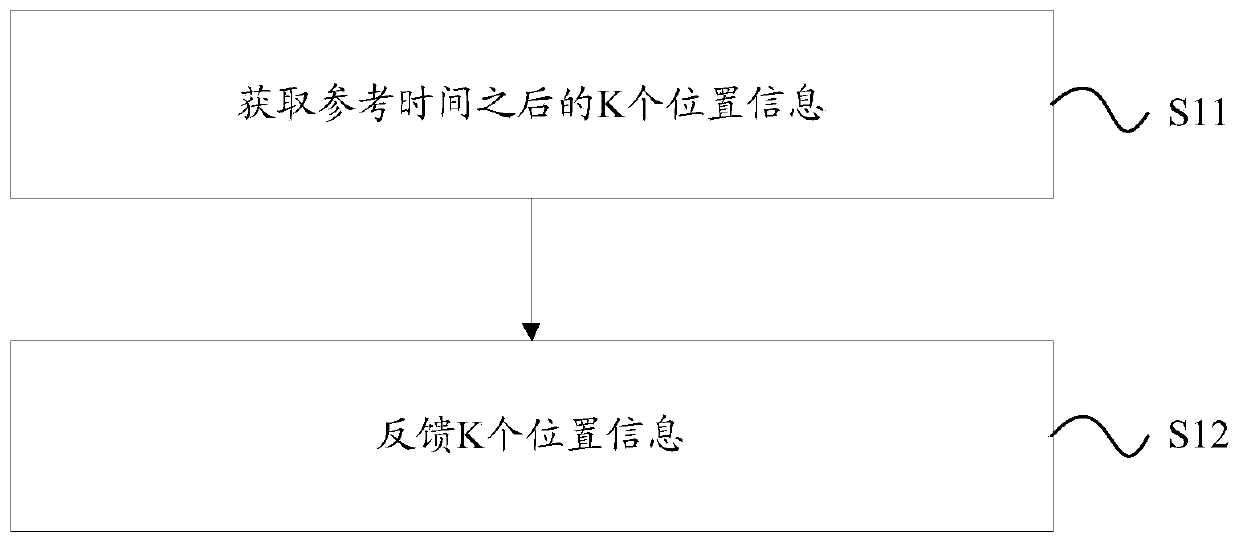
[0116] Figure 6 It is a schematic diagram of an exemplary implementation of the information feedback method provided in the embodiment of the present application. When the exemplary embodiment is applied in a system including at least one terminal (or user) and a base station, both the base station and the terminal in this system may have more than one port or antenna. Such as Figure 6 As shown, this exemplary embodiment includes the following processing:
[0117] S101. The terminal acquires K pieces of location information after a reference time; wherein, K is an integer greater than or equal to 1.
[0118] Wherein, the K pieces of location information after the reference time may refer to K pieces of location information corresponding to K moments in the future after the current moment.
[0119] Wherein, the location information may include but not limited to one of the following: Reference Signal Time Difference (RSTD), relative time of arrival (Relative Time Of Arriva...
Embodiment 2
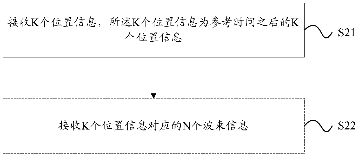
[0139] Figure 7 It is a schematic diagram of another exemplary implementation of the information feedback method provided in the embodiment of the present application. This exemplary embodiment is applied in a system including at least one terminal (or user) and a base station, and both the base station and the terminal in this system may have more than one port or antenna. Such as Figure 7 As shown, this exemplary embodiment includes the following processing:
[0140] S201. The base station acquires K pieces of location information after a reference time; wherein, K is a positive integer.
[0141] Wherein, the base station may obtain the K pieces of location information by receiving the K pieces of location information fed back by the terminal; or, may also obtain the K pieces of location information by itself through uplink channel information.
[0142] Wherein, the K pieces of location information after the reference time may refer to K pieces of location information c...
Embodiment 3
[0163] This embodiment is applied in a system including at least one terminal (or user) and a base station, and both the base station and the terminal in this system may have more than one port or antenna. In this embodiment, the terminal can improve the performance of the system through the following methods:
[0164] S301. The terminal acquires N beam information after a reference time.
[0165] Wherein, the N beam information after the reference time may refer to the N beam information corresponding to K moments in the future after the current moment; where K and N are both positive integers, and N is greater than or equal to K.
[0166] Exemplarily, the terminal may further feed back the RSRP, SINR, differential RSRP, and differential SINR corresponding to the N beam information to the base station.
[0167] Exemplarily, the N beam information is adjacent beams.
[0168] Exemplarily, the terminal may determine N beam information through downlink channel information.
[...
PUM
 Abstract
Description
Claims
Application Information
 - R&D
- Intellectual Property
- Life Sciences
- Materials
- Tech Scout
- Unparalleled Data Quality
- Higher Quality Content
- 60% Fewer Hallucinations
Browse by: Latest US Patents, China's latest patents, Technical Efficacy Thesaurus, Application Domain, Technology Topic, Popular Technical Reports.
© 2025 PatSnap. All rights reserved.Legal|Privacy policy|Modern Slavery Act Transparency Statement|Sitemap|About US| Contact US: help@patsnap.com


