BAR structure capable of increasing placement quantity

A technology of quantity and chip structure, applied in the field of laser BAR bars, can solve problems such as easy damage and contamination, small number of BAR bars, affecting quality, etc., to improve the yield rate and production efficiency, and solve the problem of insufficient coating capacity. , The effect of low processing cost

Pending Publication Date: 2019-12-03
全磊光电股份有限公司
View PDF0 Cites 0 Cited by
  • Summary
  • Abstract
  • Description
  • Claims
  • Application Information

AI Technical Summary

Problems solved by technology

The existing method is to place the BAR bar and the side bar on a piece of glass, which can only ensure that the upper end has a protrusion, and the lower end is flush with the side bar. The lower end of the BAR bar is in direct contact with the glass sheet, and it is prone to damage and Dirty, and the non-protruding end is prone to film adhesion during coating. When the BAR strips are separated, the film layer will be damaged, and the yield rate will decrease. How to ensure the ridge strips when the BAR strips are placed The integrity of the optical dielectric film layer has become the focus and difficulty of research
[0004] The existing problems are as follows: 1. When placing the BAR strips, a spatula will be placed between the BAR strips. After the coating is finished, the spatula cannot be used again, resulting in waste and high cost; Damage will easily cause the optical dielectric film at both ends of the BAR strip to be incomplete and affect the quality; 3. The number of BAR strips placed is not large, and the optical coating production capacity is low

Method used


Image

  • BAR structure capable of increasing placement quantity
  • BAR structure capable of increasing placement quantity

Examples


Embodiment

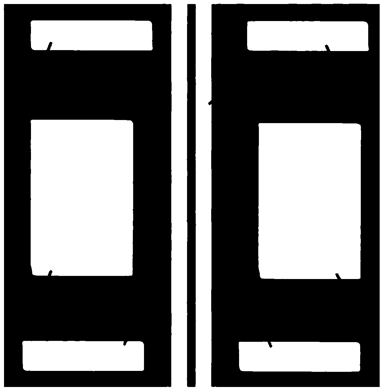
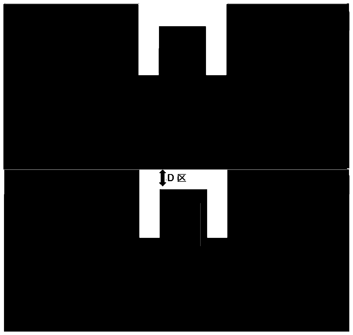
[0020] Example: as figure 1 ~ figure 2 As shown, a BAR bar structure that can increase the number of placements is formed. The BAR bar is connected by several chip structures. The middle part of the chip structure is provided with a long strip-shaped ridge area, and the two ends of the ridge area respectively extend to the Edges at both ends of the chip structure; the chip structure on both sides of the ridge region is provided with a first metal region, the two first metal regions are symmetrically arranged with respect to the ridge region, and a second metal region is arranged on one side of the first metal region , the two second metal regions are respectively arranged symmetrically on both sides of the ridge stripe region; the heights of the first metal region and the second metal region are both greater than the height of the ridge stripe region. The ridge area includes a raised ridge in the middle and grooves on both sides, and the upper layer of the ridge area is pro...


PUM


Abstract

The invention provides a BAR structure capable of increasing placement quantity. A BAR is formed by connecting a number of chip structures. A long ridge stripe region is arranged in the middle of eachchip structure, and two ends of the ridge stripe region extend to the edges of two ends of the chip structure respectively. The chip structures on both sides of each ridge stripe region are providedwith a first metal region respectively. Two first metal regions are arranged symmetrically with respect to each ridge stripe region. A second metal region is arranged on one side of each first metal region. Two second metal regions are arranged symmetrically on both sides of each ridge stripe region. The height of each first metal region and each second metal region is greater than the height of each ridge stripe region. According to the invention, the BAR strip structure has the advantages of simple structure, low processing cost and high practicability, does not need to change operation procedures, and does not need additional investment equipment; the placement quantity of BAR optical coatings can be easily, conveniently and reliably improved; accompanying bars are eliminated; the problems of insufficient coating production capacity and the problem of peeling of a spine film layer at the time of bar removing are avoided; and the yield and the production efficiency are greatly improved.

Description

technical field [0001] The invention relates to a laser BAR bar, in particular to a BAR bar structure capable of increasing the number of placements. Background technique [0002] At present, the preparation of semiconductor lasers for optical communication represents the development direction of advanced micro-nano processing and device integration technology, and has been highly valued by various countries in the world. Semiconductor lasers for optical communication are the core of optical fiber communication. At present, semiconductor lasers for optical communication mainly use INP substrates for epitaxial growth and back-end processing. In the back-end processing, the optical coating process on the end face of BAR strips is a key process to ensure laser parameters. [0003] The optical coating of BAR strips is to coat the corresponding optical dielectric film on both ends of the BAR strips. In order to ensure the coating quality during the coating process, the BAR strips...

Claims


Application Information

Patent Timeline
Patent Type & Authority Applications(China)
IPC IPC(8): H01S5/02H01S5/028
CPCH01S5/02H01S5/028
Inventor 王忠政张永单智发
Owner 全磊光电股份有限公司
Why Eureka
Try Eureka