Tire crane auxiliary system and control method
An auxiliary system and control method technology, applied in the direction of load suspension components, fluid pressure actuators, servo motors, etc., can solve the problems of multi-action compounding, system energy waste, and inability to adjust speed, etc., to achieve flow Prioritize allocation, avoid waste, and improve system responsiveness
- Summary
- Abstract
- Description
- Claims
- Application Information
AI Technical Summary
Problems solved by technology
Method used
Image
Examples
Embodiment 1
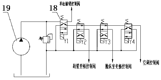
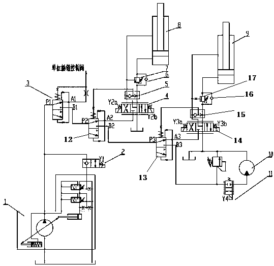
[0034] to combine figure 2 As shown, a tire crane auxiliary system,
[0035] The constant pressure pump 1 is connected to the two-position two-way valve 2, and the oil outlet of the constant pressure pump 1 is connected to the first priority valve 3;
[0036] The first priority valve 3 is respectively connected to the single-cylinder latch control valve and a second priority valve 12;
[0037] The second priority valve 12 is respectively connected to the electric proportional three-position four-way valve II4 and the third priority valve 13;
[0038] The electric proportional three-position four-way valve Ⅱ4 is connected to the rod chamber and the rodless chamber of the jib luffing cylinder 8, and is used to control the running speed of the action; The shuttle valve Ⅱ5 is connected between them, and the shuttle valve Ⅱ5 feeds back to the spring chamber of the second priority valve 12 to regulate the flow of the second priority valve 12; Sequence valve Ⅱ7 is installed on th...
Embodiment 2
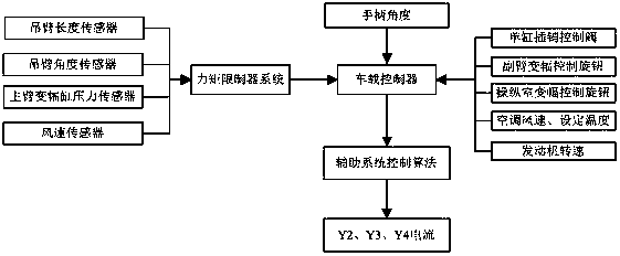
[0058] On the basis of the first embodiment above, combined with image 3 As shown, a control method of a tire crane auxiliary system,
[0059] If the operator reaches the maximum position of the operating knob for controlling the speed during actual use, then,
[0060] The first priority valve 3 is used to ensure that the single-cylinder pin control valve reaches the maximum required flow rate;
[0061] The control current of the electric proportional three-position four-way valve II4, electric proportional three-position four-way valve III14, and electric proportional two-position two-way valve IV11 is proportionally reduced by the on-board controller to adapt to the maximum displacement of the constant pressure pump 1.
[0062] The specific control steps of the on-board controller, combined with image 3 as shown,
[0063] 1. The boom length sensor, boom angle sensor, main boom luffing cylinder pressure sensor and wind speed sensor transmit the detection data to the torq...
PUM
 Abstract
Description
Claims
Application Information
 - R&D
- Intellectual Property
- Life Sciences
- Materials
- Tech Scout
- Unparalleled Data Quality
- Higher Quality Content
- 60% Fewer Hallucinations
Browse by: Latest US Patents, China's latest patents, Technical Efficacy Thesaurus, Application Domain, Technology Topic, Popular Technical Reports.
© 2025 PatSnap. All rights reserved.Legal|Privacy policy|Modern Slavery Act Transparency Statement|Sitemap|About US| Contact US: help@patsnap.com


