Wheel Crane Auxiliary System and Control Method

An auxiliary system and control method technology, applied in the direction of load suspension components, servo motors, servo motor components, etc., can solve the problems of inability to adjust speed, inability to realize multi-action compounding, system energy waste, etc., so as to avoid waste and realize Prioritize traffic distribution and improve system responsiveness

Active Publication Date: 2021-01-22
JIANGSU VOCATIONAL INST OF ARCHITECTURAL TECH
View PDF13 Cites 0 Cited by
  • Summary
  • Abstract
  • Description
  • Claims
  • Application Information

AI Technical Summary

Problems solved by technology

[0005] (1) The power source is shared by multiple circuits, and the combination of multiple actions cannot be realized;
[0006] (2) Actions such as jib luffing, control room luffing, and air conditioning can only move at a constant speed and cannot be adjusted;
[0007] (3) Regardless of the flow rate required by the system, the quantitative pump always outputs a constant flow rate, resulting in a waste of system energy

Method used


Image

  • Wheel Crane Auxiliary System and Control Method
  • Wheel Crane Auxiliary System and Control Method
  • Wheel Crane Auxiliary System and Control Method

Examples


Embodiment 1

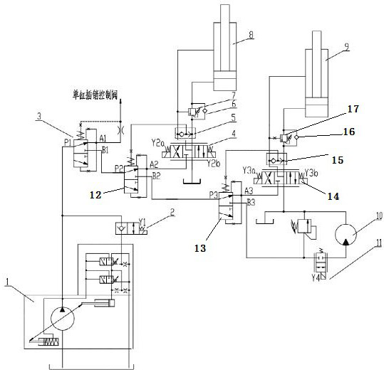
[0034] combine figure 2 As shown, a tire crane auxiliary system,

[0035] The constant pressure pump 1 is connected to the two-position two-way valve 2, and the oil outlet of the constant pressure pump 1 is connected to the first priority valve 3;

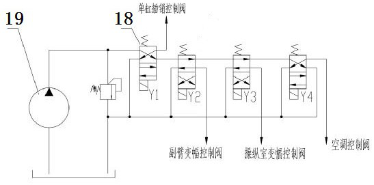
[0036] The first priority valve 3 is respectively connected to the single-cylinder latch control valve and a second priority valve 12;

[0037] The second priority valve 12 is respectively connected to the electric proportional three-position four-way valve II4 and the third priority valve 13;

[0038] The electric proportional three-position four-way valve Ⅱ4 is connected to the rod chamber and the rodless chamber of the jib luffing cylinder 8, and is used to control the running speed of the action; The shuttle valve Ⅱ5 is connected between them, and the shuttle valve Ⅱ5 feeds back to the spring chamber of the second priority valve 12 to regulate the flow of the second priority valve 12; Sequence valve Ⅱ7 is installed on the o...

Embodiment 2

[0058] On the basis of the first embodiment above, combined with image 3 As shown, a control method of a tire crane auxiliary system,

[0059] If the operator reaches the maximum position of the operating knob for controlling the speed during actual use, then,

[0060] The first priority valve 3 is used to ensure that the single-cylinder pin control valve reaches the maximum required flow rate;

[0061] The control current of the electric proportional three-position four-way valve II4, electric proportional three-position four-way valve III14, and electric proportional two-position two-way valve IV11 is proportionally reduced by the on-board controller to adapt to the maximum displacement of the constant pressure pump 1.

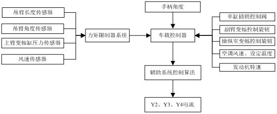
[0062] The specific control steps of the on-board controller, combined with image 3 as shown,

[0063] 1. The boom length sensor, boom angle sensor, main boom luffing cylinder pressure sensor and wind speed sensor transmit the detection data to the torq...


PUM


Abstract

The invention discloses a tire crane auxiliary system and a control method. The tire crane auxiliary system comprises a single-cylinder bolt control valve, an auxiliary arm variable-amplitude oil cylinder, a control cabin variable-amplitude oil cylinder and an air conditioner motor, a constant-pressure pump is connected with a two-position two-way valve, and an oil outlet of the constant-pressurepump is connected with the first priority valve; the first priority valve is respectively connected with the single-cylinder bolt control valve and a second priority valve, the second priority valve is respectively connected with an electric proportional three-position four-way valve II and a third priority valve,the third priority valve is respectively connected with an electric proportional three-position four-way valve III and an electric proportional two-position two-way valve IV, and the electric proportional two-position two-way valve IV is connected with the air conditioner motor. According to the present invention, different priorities are set for all the auxiliary actions, several actions can be controlled at the same time, but also the flow can be preferentially supplied to the system with the high priority. The beneficial effects are that the flow priority distribution can be better realized, so that the multi-action compounding is realized; the automatic speed regulation ofthe actions, such as fly jib amplitude variation, control cabin amplitude variation, air conditioning, etc., is realized; the responsiveness of the system is improved, and the waste of the redundantflow is avoided.

Description

technical field [0001] The invention relates to the technical field of hydraulic drive systems, in particular to a tire crane auxiliary system and a control method. Background technique [0002] As the tonnage of the tire crane increases, more and more actions are performed, so the hydraulic system is also becoming more and more complex. The tire crane hydraulic system is mainly divided into the main action system and the auxiliary action system. Due to its high operating frequency and large load, the main action system is designed to drive multiple pumps, such as slewing, telescopic, luffing, hoisting and other actions; and the auxiliary action system is used as much as possible due to its relatively low operating frequency. Fewer pumps to drive. Due to the small difference in load pressure and flow of auxiliary actions such as the single-cylinder bolt system of the telescopic oil cylinder, the jib luffing system, the control room luffing system, and the air conditioning ...

Claims


Application Information

Patent Timeline
Patent Type & Authority Patents(China)
IPC IPC(8): B66C23/62B66C23/82B66C23/693F15B11/08F15B13/02B66C13/16
CPCB66C13/16B66C23/62B66C23/701B66C23/82F15B11/08F15B13/02
Inventor 臧其亮史俊青仇文宁王国安付红张海燕徐志鹏崔洁国芳周婷
Owner JIANGSU VOCATIONAL INST OF ARCHITECTURAL TECH
Why Eureka
Try Eureka