
A pressure-free high-frequency suspension thermal transfer machine

A thermal transfer machine, high-frequency technology, applied in the direction of rotary printing machine, printing machine, transfer printing, etc., can solve the problems of long transfer printing time, inability to meet individual needs, inability to customize patterns, etc.

Active Publication Date: 2021-01-22
义乌泰乐机械设备有限公司
View PDF4 Cites 0 Cited by
  • Summary
  • Abstract
  • Description
  • Claims
  • Application Information

AI Technical Summary

Problems solved by technology

The production of flower film involves plate-making and printing. The pattern needs to be customized in large quantities to reduce the cost. Small-scale production cannot customize the pattern and cannot meet individual needs.
A small amount of custom-made patterns must use a printer. This kind of process takes a long time to transfer (more than 60 seconds), and manual hand pressure cannot persist
Therefore, these portable small devices on the market have limited limitations in personalized transfer printing.

Method used


Image

  • A pressure-free high-frequency suspension thermal transfer machine
  • A pressure-free high-frequency suspension thermal transfer machine
  • A pressure-free high-frequency suspension thermal transfer machine

Examples


Embodiment 1

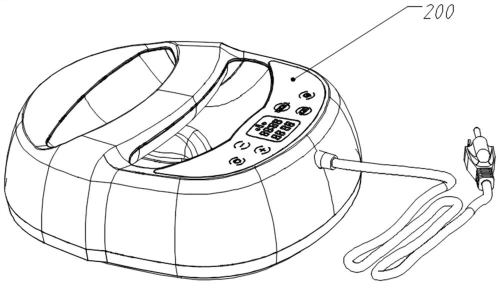
[0070] Reference attached Figure 3-8 , a pressure-free high-frequency suspension heat transfer machine, including a host assembly 200, the host assembly 200 is provided with an outer shell 201, an inner shell 202, a secondary heat insulation shell 203, a fixed shell 204, a primary The heat insulation shell 205 and the heating plate 206; the handle tray 2021 is fixed between the outer shell 201 and the inner shell 202, and the high-frequency transducer motor 406 is installed between the handle tray 2021 and the inner shell 202; the handle beam 2022 is fixed on the top of the handle tray 2021 , the handle beam 2022 is equipped with a radiator 2023, and the radiator 2023 is equipped with a control output board 403; the heating board 206 is also provided with a sudden jump temperature controller 401 and a temperature sensor 402; the rear top of the shell 201 is equipped with a central control board 404, A high-frequency switching power supply 405 is installed below the central co...

Embodiment 2

[0101] On the basis of Embodiment 1, the host assembly 200 is also equipped with a placement tray 100, and the host assembly 200 is co-located in the placement tray 100 for placement and placement;

[0102] refer to Figure 12-16 The placement tray 100 is circular and is composed of four identical quarter-arc-shaped pieces 101 with end-to-end buckles; the bottom of the placement tray 100 is provided with feet 102; Suspension 104 is housed.

[0103] The placement tray adopts the same arc-shaped block structure, only need to open a small mold during production, the overall production difficulty and cost are greatly reduced, and the packaging volume is also greatly reduced during product packaging, especially in international trade. For occasions with high requirements on transportation costs, it can reduce costs and improve product competitiveness. In addition, the circular ring on which the disk is placed is universal, so that the equipment can be placed freely during use, an...


PUM


Abstract

The invention relates to the technical field of thermal transfer printing, in particular to a pressure-free high-frequency suspension thermal transfer machine; it provides a pressure-free high-frequency suspension thermal transfer machine, which generates 60-100Hz high-frequency through a high-frequency switching power supply The signal drives the high-frequency transducing motor, converts the signal into high-frequency mechanical vibration, and generates 60-100Hz high-frequency waves. The high-frequency waves propagate in a longitudinal diffusion manner, that is, the direction vertical to the transfer surface covers the entire transfer surface, avoiding horizontal transmission. That is, the waste loss in the direction parallel to the transfer surface makes the high-frequency wave act on the molecular motion in the transfer process to the maximum extent, effectively changes the molecular motion state, enhances the molecular penetration force, realizes the replacement of physical pressure with high-frequency waves, and completely changes the thermal transfer process. Printing process, to achieve pressure-free thermal transfer.

Description

technical field [0001] The invention relates to the technical field of heat transfer printing, in particular to a pressure-free high-frequency suspension heat transfer machine. Background technique [0002] The thermal transfer process is mainly divided into two categories: sublimation thermal transfer and flower film thermal transfer: [0003] Sublimation thermal transfer printing: It is to make low-energy, easy-to-sublimate disperse dyes into digital printing inks, print them on transfer paper, and use heat and pressure to directly sublimate the ink from solid particles into gas molecules and penetrate into the transfer printing. product surface. Patterns can be made on exquisite porcelain, metal, silk, fiber fabric, cloth and other materials within 1-3 minutes. [0004] Specifically, the digital printer prints the pattern (imaging ink layer) on the printing paper (printing pattern carrier layer), which constitutes "thermal transfer sublimation paper". Cover the "sublim...

Claims


Application Information

Patent Timeline
Patent Type & Authority Patents(China)
IPC IPC(8): B41F16/00B41F16/02B41F33/00
CPCB41F16/0006B41F16/0093B41F16/02B41F33/00B41F16/0046B41M5/035B41J2/385
Inventor 何光峰
Owner 义乌泰乐机械设备有限公司
Learn More