
Cutting machine for fitness equipment production

A fitness equipment and cutting machine technology, which is applied to metal processing machinery parts, large fixed members, clamping and other directions, can solve the problems of low work efficiency and poor accuracy, and achieve the effect of improving work efficiency, high precision and easy movement.

Inactive Publication Date: 2019-12-03
TIANJIN XINGKAI SPORTS INSTR
View PDF0 Cites 5 Cited by
  • Summary
  • Abstract
  • Description
  • Claims
  • Application Information

AI Technical Summary

Problems solved by technology

In the production process of fitness equipment, a large number of pipes are used. At this time, a cutting machine is required to cut the material. However, some cutting machines cannot accurately adjust the cutting length of the steel pipes. This can only be achieved by manual measurement and marking. , not only poor accuracy, but also low work efficiency

Method used


Image

  • Cutting machine for fitness equipment production
  • Cutting machine for fitness equipment production
  • Cutting machine for fitness equipment production

Examples


Embodiment 1

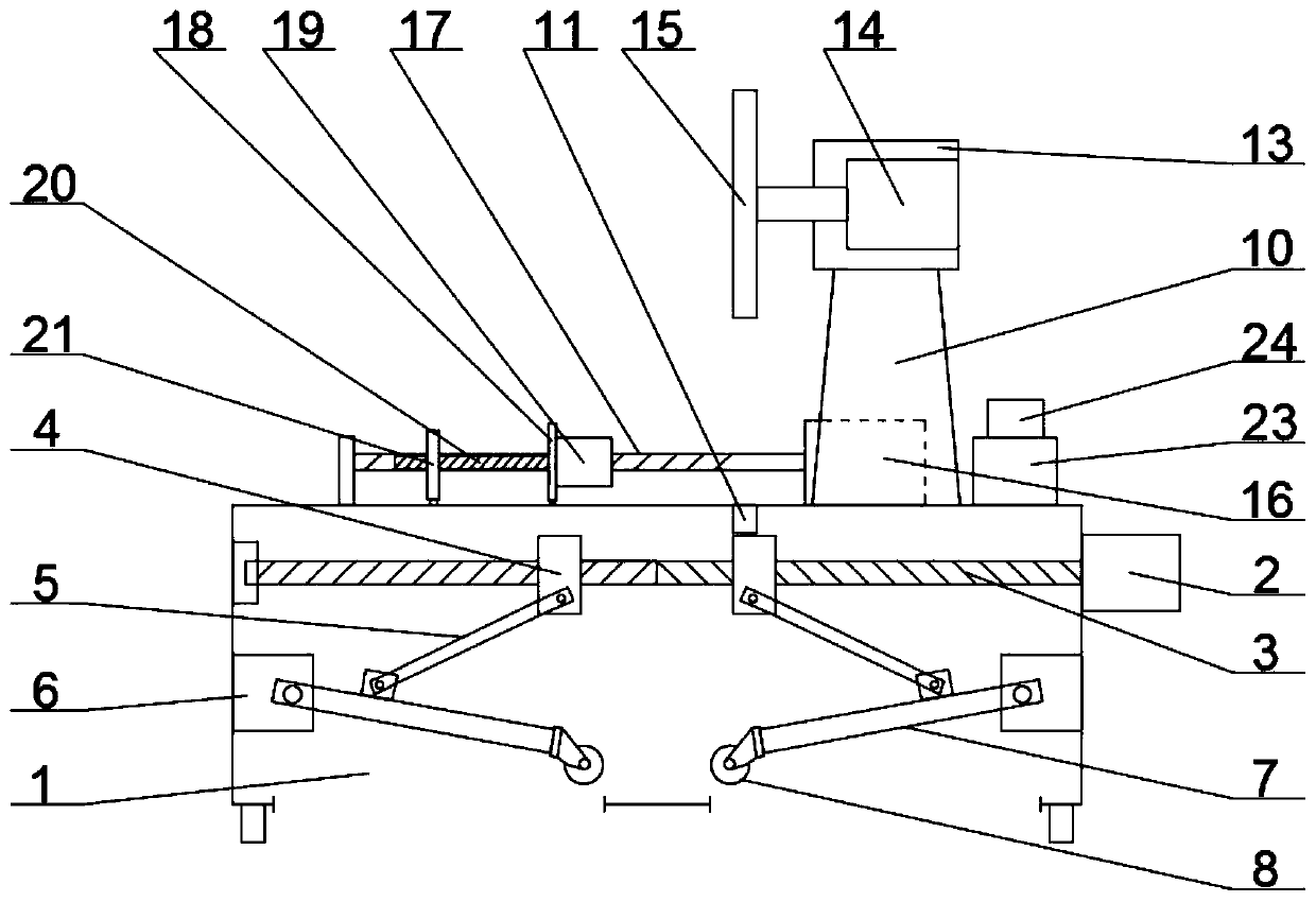
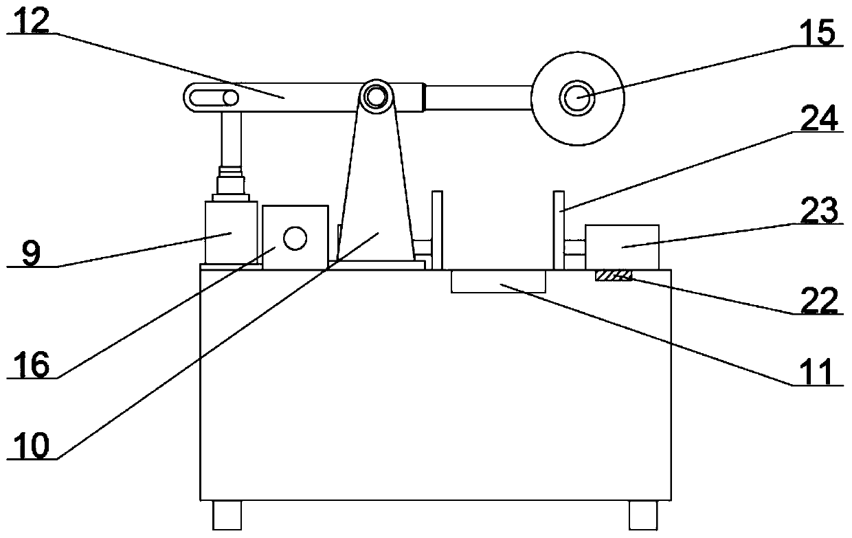
[0025] A cutting machine for fitness equipment production, comprising a base 1, the bottom surface of the base 1 is provided with legs, the outer side of the base 1 is provided with a motor D2 on the front and rear sides, and the output end of the motor D2 is provided with a penetrating base 1- The side wall and the double-rotational lifting screw 3 that is rotationally connected with the other side wall in the base 1, the two sides of the lifting screw 3 in the base 1 are screwed with a screw nut 4 and the bottom end of the screw nut 4 is hinged to connect Rod A5, the front side wall and the rear side wall in the base 1 are all provided with a support block 6 and the support block 6 is hinged with a connecting rod B7, the support block 6 is located below the lifting screw 3, and the connecting rod A5 is away from One end of the screw nut 4 is hinged with the connecting rod B7, and the end of the connecting rod B7 away from the support block 6 is provided with a moving wheel 8 ...

Embodiment 2

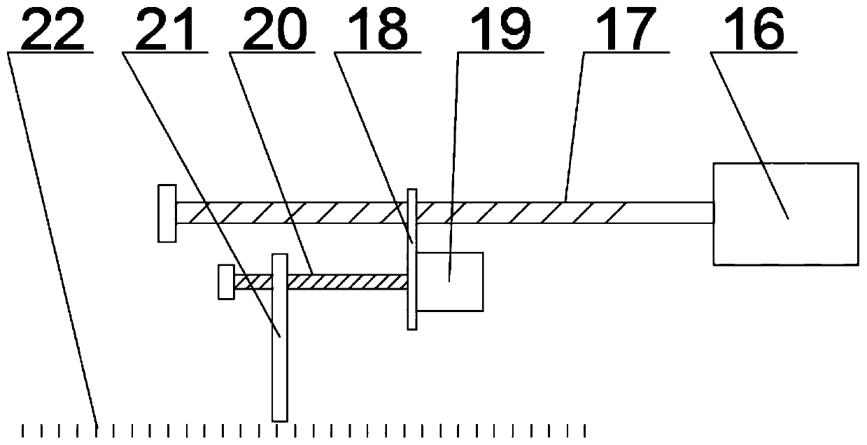
[0031]A cutting machine for fitness equipment production, comprising a base 1, the bottom surface of the base 1 is provided with legs, the outer side of the base 1 is provided with a motor D2 on the front and rear sides, and the output end of the motor D2 is provided with a penetrating base 1- The side wall and the double-rotational lifting screw 3 that is rotationally connected with the other side wall in the base 1, the two sides of the lifting screw 3 in the base 1 are screwed with a screw nut 4 and the bottom end of the screw nut 4 is hinged to connect Rod A5, the front side wall and the rear side wall in the base 1 are all provided with a support block 6 and the support block 6 is hinged with a connecting rod B7, the support block 6 is located below the lifting screw 3, and the connecting rod A5 is away from One end of the screw nut 4 is hinged with the connecting rod B7, and the end of the connecting rod B7 away from the support block 6 is provided with a moving wheel 8 a...


PUM


Abstract

The invention discloses a cutting machine for fitness equipment production. The cutting machine comprises a base; a motor D, a double-rotation-direction lifting lead screw, a nut, a connecting rod A,a connecting rod B, moving wheels, a hydraulic cylinder A, a support, a cutting groove, a movable rod, a motor B, a cutting blade, a measuring and positioning device and a workpiece clamping device are arranged on the base. By arranging the connecting rods, the lifting lead screw and the motor D, the machine is convenient to move; meanwhile, due to the arrangement of the measuring and positioningdevice, the cutting length of a steel pipe can be accurately adjusted, the accuracy is high, and the working efficiency is improved; and finally, the workpiece clamping device can clamp the workpiece,and reduction of the cutting quality caused by sliding of the workpiece during cutting is avoided.

Description

technical field [0001] The invention relates to the technical field of cutting machines, in particular to a cutting machine for fitness equipment production. Background technique [0002] In the process of mechanical processing, cutting machines are usually used to cut plates or pipes. Cutting machines are developing more and more rapidly today, and they are also very common in our life and work. In the production process of fitness equipment, a large number of pipes are used. At this time, a cutting machine is required to cut the material. However, some cutting machines cannot accurately adjust the cutting length of the steel pipes. This can only be achieved by manual measurement and marking. , not only poor accuracy, but also low work efficiency. Contents of the invention [0003] The invention aims to solve the deficiencies of the prior art, and provides a cutting machine for fitness equipment production. [0004] In order to achieve the above object, the present inve...

Claims


Application Information

Patent Timeline
Patent Type & Authority Applications(China)
IPC IPC(8): B23D79/00B23Q1/01B23Q3/06B23Q5/26B23Q17/22
CPCB23D79/00B23Q1/01B23Q3/06B23Q5/26B23Q17/22
Inventor 李振凯
Owner TIANJIN XINGKAI SPORTS INSTR
Learn More