
Method for training switching parameters of a magnetic control valve in a vehicle braking system and braking system

A technology for switching parameters and braking systems, applied in braking safety systems, general control systems, braking control systems, etc., can solve problems such as inaccurate driving and control of service brakes, inability to compensate tolerances, and asymmetric driving and control

Active Publication Date: 2021-10-08
ZF CV SYST EURO BV
View PDF16 Cites 0 Cited by
  • Summary
  • Abstract
  • Description
  • Claims
  • Application Information

AI Technical Summary

Problems solved by technology

The disadvantage is that tolerances in the brake system of the vehicle in which such magnetic control valves are installed, for example due to differently configured piping or volumes of the brake cylinders, are not taken into account and thus cannot be compensated for.
[0009] The disadvantage is that the switching parameters of the magnetic control valve upstream of the service brake in the modulator cannot be deduced even if the response pressure of the service brake is known
However, this may differ slightly from the actual switching parameters, for example due to the environment or due to the design of the current braking system, which may lead to an inaccurate actuation of the service brakes, e.g. undesirably asymmetric drive

Method used


Image

  • Method for training switching parameters of a magnetic control valve in a vehicle braking system and braking system
  • Method for training switching parameters of a magnetic control valve in a vehicle braking system and braking system
  • Method for training switching parameters of a magnetic control valve in a vehicle braking system and braking system

Examples


Embodiment Construction

[0049] specific implementation plan

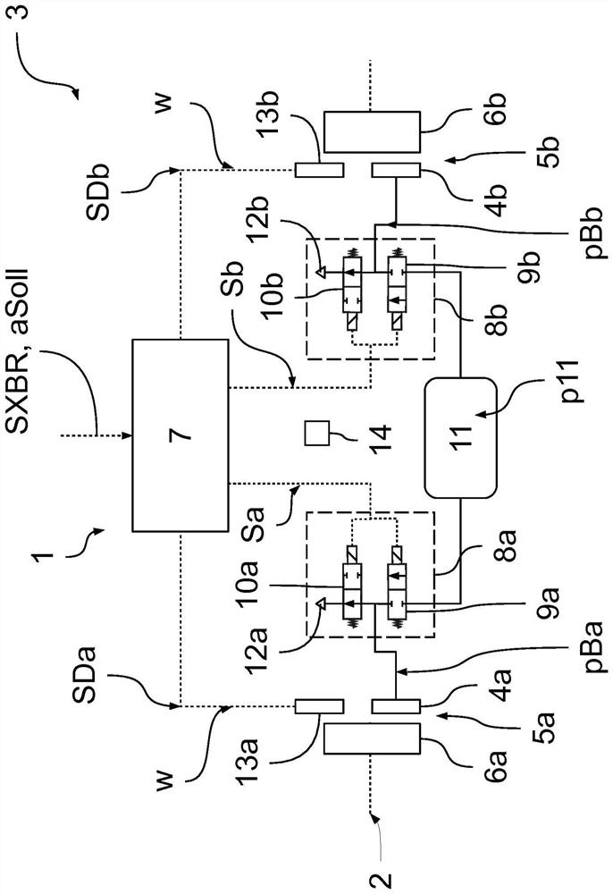
[0050] figure 1 An exemplary and schematic fragment of a braking system 1 in the region of the rear axle 2 of a vehicle 3 is shown, wherein the braking system 1 is embodied according to this embodiment as a pneumatic braking system. The respective wheels 6a, 6b on the rear axle 2 can thus be braked in a targeted manner by building up brake pressures pBa, pBb in the brake cylinders or brake chambers 4a, 4b of the service brakes 5a, 5b. Here, the designations "a" and "b" distinguish the wheel sides of the rear axle 2, wherein "a" designates the left side and "b" designates the right side.

[0051] Presetting of the braking pressures pBa, pBb in the service brakes 5a, 5b on the rear axle 2 is realized electropneumatically, specifically, the control device 7 of the braking system 1 uses the control signal Sa, Sb to control the respective service brakes Modulators 8a, 8b before 5a, 5b. according to figure 1 Each modulator 8a, 8b has an inle...


PUM


Abstract

The invention relates to a method for training switching parameters of magnetic control valves (9a, 9b, 10a, 10b) in a braking system (1) of a vehicle (3), the method having at least the following steps: - determining the vehicle test acceleration; - learning At least two test pulse sequences (PF1, PF2), wherein the test pulses are determined in dependence on the determined vehicle test acceleration and on the initial value of the switching parameter for the respective magnetic control valve (9a, 9b, 10a, 10b), respectively sequence (PF1, PF2), and the test pulse sequence (PF1, PF2) has actuation pulses and non-actuation pulses, wherein the respective magnetic control valves (9a, 9b, 10a, 10b) are enabled during the actuation pulses, and Deactivate the respective magnetic control valve (9a, 9b, 10a, 10b) during the non-actuation pulse, - actuate the magnetic control valve (9a, 9b, 10a, 10b) with at least two test pulse sequences (PF1, PF2) to bring about at least two test brakes, wherein the brake pressure (pBa, pBb) on the service brakes (5a, 5b) of the brake system (1) is brought about by a respective test pulse sequence (PF1, PF2) change, so as to obtain the change of the driving dynamics (w, w1, w2) of the vehicle (3), and obtain the driving dynamics variation to detect the vehicle ( 3) changes in the driving dynamics (w1, w2), and - adjust the switching parameter initial values ​​for the magnetic control valves (9a, 9b, 10a, 10b) in order to train the magnetic control valves (9a, 9b, 10a, 10b) switching parameters.

Description

technical field [0001] The invention relates to a method for training switching parameters of a magnetic control valve in a vehicle braking system and to a braking system with a magnetic control valve, which is suitable for carrying out the method. Background technique [0002] Service brake systems are known as pneumatic or hydraulic operating systems, which can also distribute specific brake pressures to the brake cylinders of the service brake in an electrically controlled manner via corresponding modulators. For this purpose, magnetic control valves are arranged in the modulators which are arranged upstream of the respective brake cylinders of the respective service brakes, via which brake pressures can be built up in the respective brake cylinders as a function of the control signal . For this purpose, the stored pressure from the pressure medium store can be fed into the brake cylinder via an inlet valve designed as a magnetic control valve, in order to increase the b...

Claims


Application Information

Patent Timeline
IPC IPC(8): B60T17/22
CPCB60T17/221G01R31/006B60T8/171B60T8/174B60T15/025B60T2250/00B60T2270/406G01P3/00G01P15/00G05B13/0265G05B13/042
Inventor 托马斯·迪克曼塞巴斯蒂安·库内安德里亚斯·格斯拉尔夫-卡斯滕·吕尔芬奥利弗·伍尔夫
Owner ZF CV SYST EURO BV
Learn More