
System and method for testing tensile strength distribution condition of explosive structural member

A technology for tensile strength and structural parts, which is applied in the field of test systems for the distribution of tensile strength of explosive structural parts, can solve the problems of long sample preparation period, long sample time, and high time cost, and achieve high test efficiency, The effect of less sample consumption and short preparation period

Inactive Publication Date: 2019-11-29
INST OF CHEM MATERIAL CHINA ACADEMY OF ENG PHYSICS
View PDF6 Cites 0 Cited by
  • Summary
  • Abstract
  • Description
  • Claims
  • Application Information

AI Technical Summary

Problems solved by technology

However, on the one hand, since the crack initiation position of the sample in the Brazilian test is not in a uniaxial stress state, the test error for nonlinear elastic materials and materials related to hydrostatic pressure is relatively large; The cycle is long, the sample time is long, and the time cost is huge

Method used


Image

  • System and method for testing tensile strength distribution condition of explosive structural member
  • System and method for testing tensile strength distribution condition of explosive structural member
  • System and method for testing tensile strength distribution condition of explosive structural member

Examples


Embodiment 1

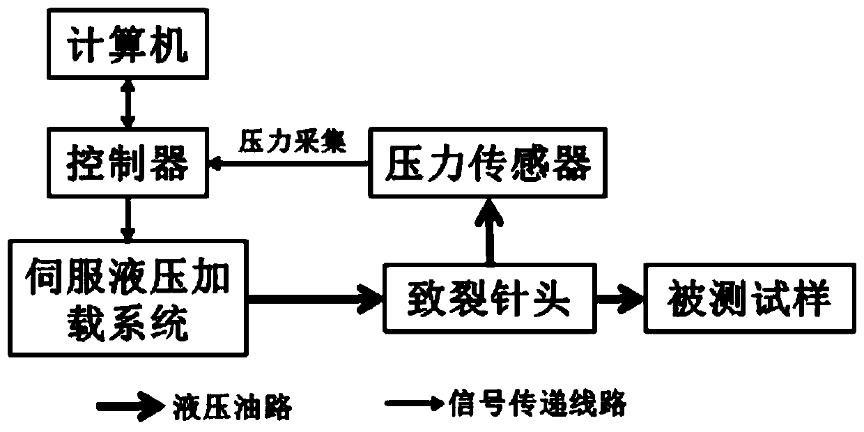
[0021] Such as figure 1 As shown, the present invention provides a test system for the distribution of tensile strength of explosive structural parts, the system includes a computer, a controller, a servo hydraulic loading system, a cracking needle and a pressure sensor, and the computer is used to pressurize The command is sent to the controller, and the controller is used to send the command to the servo hydraulic loading system, and the servo hydraulic loading system is used to apply pressure to the cracking needle, and the cracking needle acts on the explosive structure to cause cracking The pressure change at the needle is collected to the controller through the pressure sensor and fed back to the computer by the controller.

Embodiment 2

[0023] A method for testing the tensile strength distribution of explosive structural parts, specifically, first mechanically dissecting explosive structural parts into small pieces of arbitrary shape (satisfying that the effective size is greater than 1.5 times the aperture) and recording the position information of each piece of explosive, and then testing each piece Finally, the tensile strength data of each sample and the position information are combined to obtain the distribution of the tensile strength of the explosive structure. The testing process of each sample is as follows: First, a hole with a certain depth and the diameter of the cracking needle is drilled on the sample, and the cracking needle is put into the hole and the hole is sealed. The pressurization command is sent to the controller through the computer, and the controller then sends the command to the execution unit (servo hydraulic loading system), and the hydraulic oil is transmitted to the cracking nee...


PUM


Abstract

The invention discloses a system and a method for testing a tensile strength distribution condition of an explosive structural member. The system comprises a computer, a controller, a servo hydraulicloading system, a fracturing needle head and a pressure sensor; the computer is used for sending a pressurizing command to the controller; the controller is used for sending the command to the servo hydraulic loading system; the servo hydraulic loading system is used for applying a pressure to the fracturing needle head; the fracturing needle head acts on the explosive structural member; and the pressure change at the fracturing needle head is collected to the controller through the pressure sensor and is fed back to the computer by the controller. The method has the advantages of short samplepreparation period, simple testing, no special requirements on the morphology of a sample and the like; and the tensile strength distribution condition of the explosive structural member can be rapidly tested under the condition that the testing precision is ensured.

Description

technical field [0001] The invention relates to the technical field of structural mechanics, in particular to a testing system and method for the tensile strength distribution of explosive structural parts. Background technique [0002] Polymer bonded explosive (Polymer Bonded Explosive, PBX) is widely used in shells, nuclear weapons, missiles and other warheads. Explosive structure of a certain configuration. In order to accurately design, evaluate, and check the bearing capacity of explosive structural parts, it is necessary to obtain the distribution of mechanical properties including material strength in explosive structural parts. Since the tensile strength of explosive materials is much smaller than the compressive strength, accurate testing of their tensile strength is even more important. The current testing methods for the tensile strength of explosive materials mainly include the direct tension method and the indirect tension method based on dumbbell specimens. ...

Claims


Application Information

Patent Timeline
IPC IPC(8): G01N3/12
CPCG01N3/12G01N2203/0019G01N2203/0048
Inventor 袁洪魏唐维董天宝颜熹琳颜学坚赵龙
Owner INST OF CHEM MATERIAL CHINA ACADEMY OF ENG PHYSICS
Learn More