Stress loading combination device

A combined device and stress loading technology, which is applied in the direction of measuring devices, using stable tension/pressure to test the strength of materials, instruments, etc., can solve the problems of complex principles, high development costs, and increased research difficulty, so as to reduce test errors, Good test effect and easy operation

Pending Publication Date: 2019-11-29
GUANGDONG UNIV OF TECH
View PDF0 Cites 2 Cited by
  • Summary
  • Abstract
  • Description
  • Claims
  • Application Information

AI Technical Summary

Problems solved by technology

However, the principle of the existing true triaxial compression testing machine is relatively complicated, and the development cost is relatively high. There are only a few high-efficiency or institutions in China, which increases the difficulty of research.

Method used


Image

  • Stress loading combination device
  • Stress loading combination device
  • Stress loading combination device

Examples


Embodiment 1

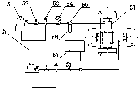
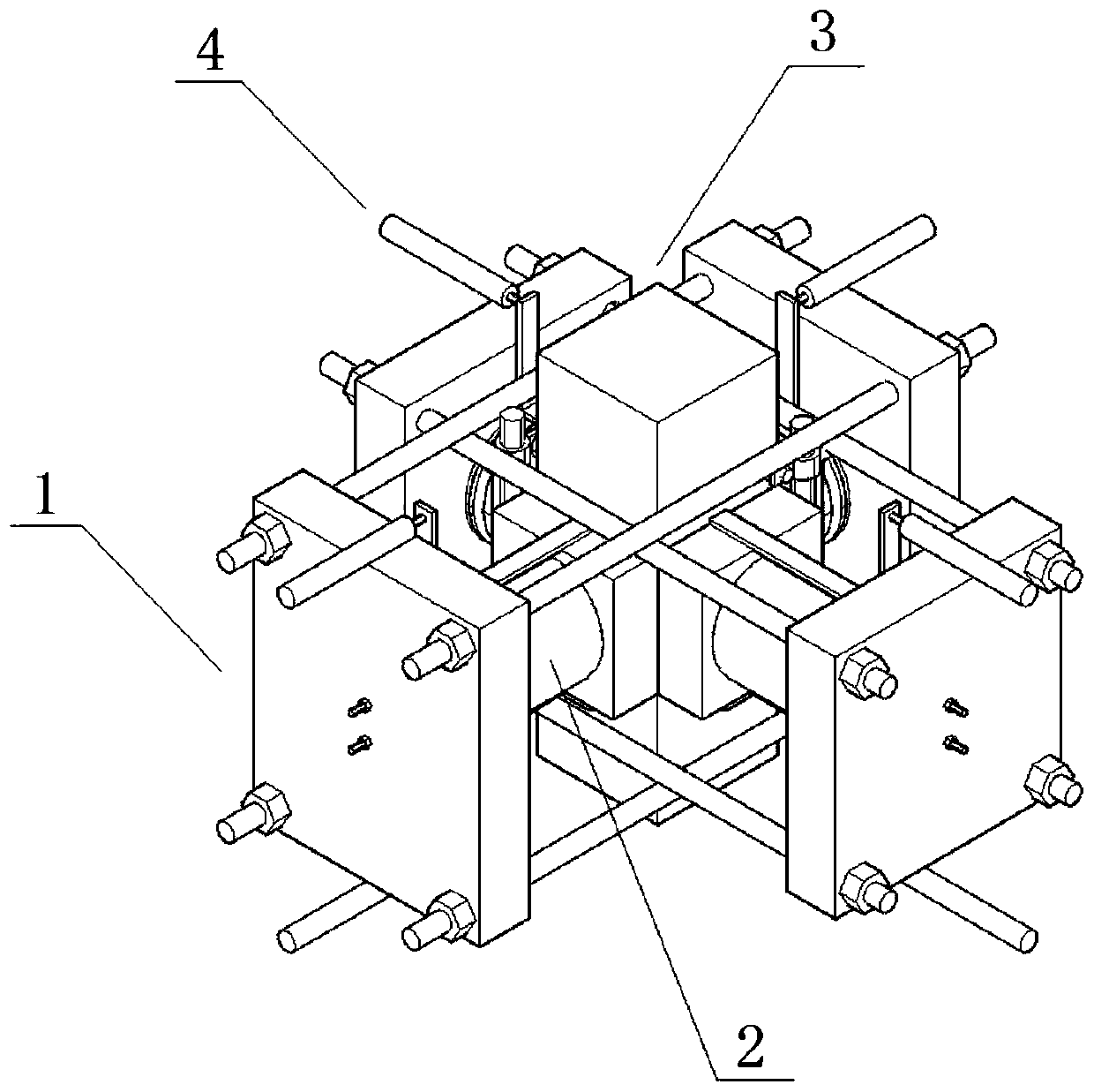
[0033] Such as Figure 1 to Figure 7 Shown is a first embodiment of a stress loading combination device of the present invention, which is used to place on the loading platform of a uniaxial servo press 8 to perform a true triaxial pressure test on a cube specimen 7, and the device includes two mutual The first loading assembly 1 vertically arranged for the circumferential force transmission of the cube test piece 7, and the second loading assembly 3 for the axial force transmission of the cube test piece 7; the first loading assembly 1, the second loading assembly 3 are in close contact with the circumferential surface and the axial surface of the cube specimen 7 respectively; the first loading assembly 1 is connected with the force applying mechanism 2, and the force applying mechanism 2 is connected with the control system 5, the first loading assembly 1 and the second Displacement measuring components 4 are arranged on the loading components 3 .

[0034] The force applyin...

Embodiment 2

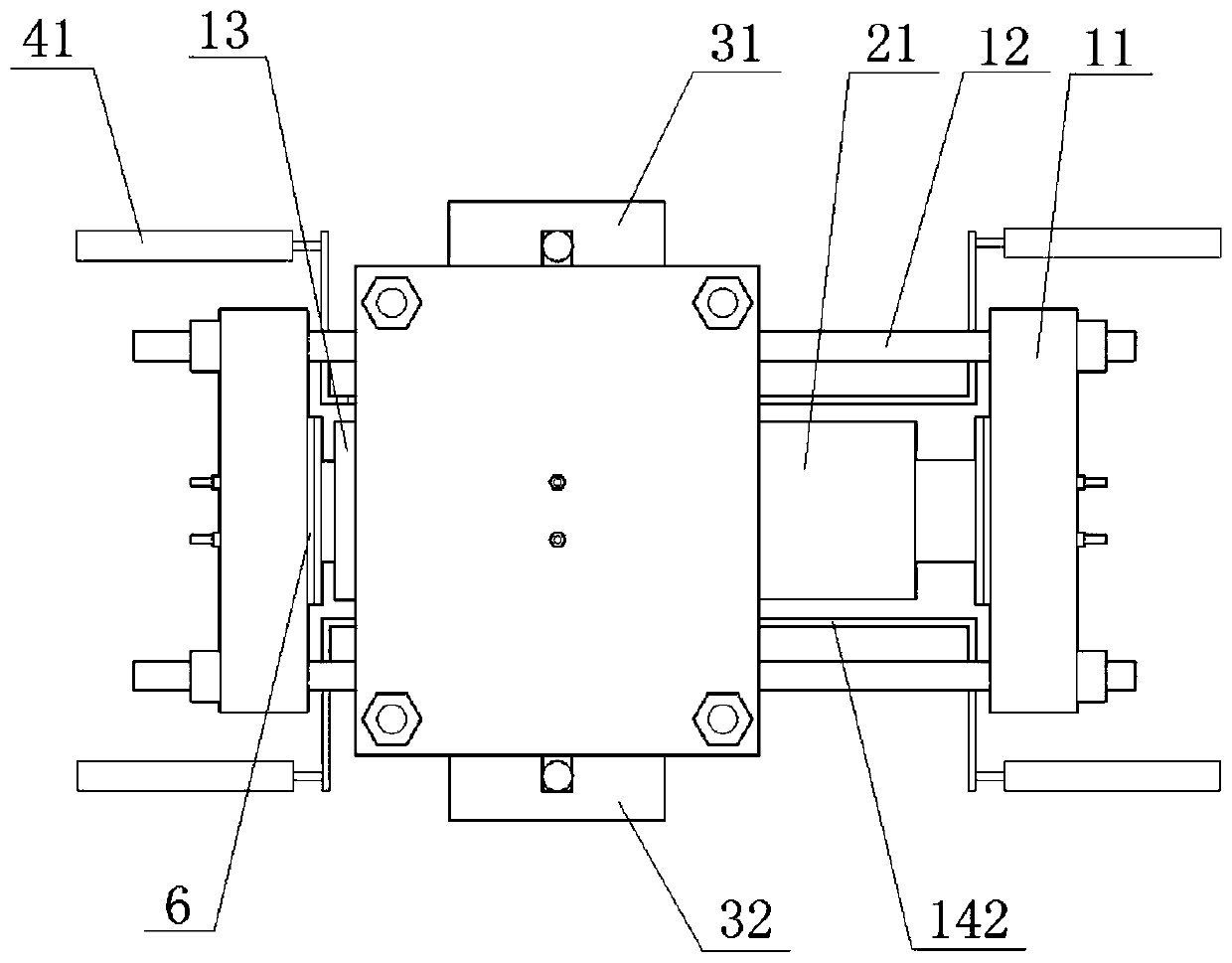
[0068] This embodiment is similar to Embodiment 1, the difference is that, as Figure 2 to Figure 4 As shown, in this embodiment, thin sheets for reducing friction are provided between the second pressing plate 141 , the first pressing block 31 , the second pressing block 32 and the cube test piece 7 . The arrangement of thin slices can reduce the friction between the first loading assembly 1 , the second loading assembly 3 and the cube specimen 7 .

[0069] In addition, a gasket 6 for reducing stress concentration is provided between the force applying mechanism 2 , the first pressing plate 13 and the end plate 11 . The arrangement of the gasket 6 can prevent the stress from concentrating on the cube test piece 7 .

[0070] Specifically, as Figure 2 to Figure 5 As shown, the sheet in this embodiment is a polytetrafluoroethylene sheet, and the gasket 6 is a steel gasket.

[0071] In step S2, after the polytetrafluoroethylene sheet is placed on the upper surface of the seco...


PUM

PropertyMeasurementUnit
Side lengthaaaaaaaaaa

Abstract

The invention relates to the technical field of building material test equipment, in particular to a stress loading combination device. The device is used for being placed on a loading platform of a uniaxial servo press to perform a true triaxial pressure test on a cubic test piece. The device comprises two groups of first loading components and second loading components, wherein the first loadingcomponents are arranged perpendicular to each other and are used for transmitting force in a circumferential direction of the cubic test piece, and the second loading components are used for transmitting force in an axial direction of the cubic test piece; the first loading components and the second loading components make close contact with a circumferential surface and an axial surface of the cubic test piece respectively; and a force application mechanism is connected to each first loading component, a control system is connected to each force application mechanism, and displacement measurement components are arranged on the first loading components and the second loading components respectively. Through the device, restraint stress can be precisely controlled, manufacturing cost is low, operation is easy, and the application range is wide.

Description

technical field [0001] The invention relates to the technical field of building material testing equipment, and more particularly, to a stress loading combination device. Background technique [0002] Various building materials are often subjected to multi-directional stresses in practical applications. Understanding their mechanical properties, failure modes, and constitutive relations under this condition has important guiding significance for their application in practical engineering. Among them, the true triaxial compressive stress state, that is, the material is subjected to compressive stresses that are not necessarily equal in magnitude on the three principal stress axes, represents a wide range of real engineering applications, such as steel tube concrete structures, fiber reinforced polymer confined concrete structures , nuclear reactor high-pressure container concrete structure, high-rise large-scale concrete components, soil or rock below the surface, etc. Howev...

Claims


Application Information

Patent Timeline
IPC IPC(8): G01N3/10G01N3/02
CPCG01N3/10G01N3/02G01N2203/0003G01N2203/0019G01N2203/0048G01N2203/0256
Inventor 欧阳祎曾振华郭永昌曾俊杰
Owner GUANGDONG UNIV OF TECH
Why Eureka
Try Eureka