A multi-level protection pneumatic reciprocating saw

A technology of reciprocating saw and cylinder, applied in the field of multi-level protection pneumatic reciprocating saw, can solve the problems of low safety performance, time-consuming and laborious, centrifugal motion, etc., and achieve the effect of improving safety, simple principle and improving efficiency.

Active Publication Date: 2020-08-07
永康市亿科锯业有限公司
View PDF8 Cites 0 Cited by
  • Summary
  • Abstract
  • Description
  • Claims
  • Application Information

AI Technical Summary

Problems solved by technology

[0002] Saw is one of the common tools in daily life. It is mainly used for cutting wood, etc. According to the classification of driving power, it can be roughly divided into two categories. One is manual saw, which mainly includes the saw body and The saw blade is composed of manually pulling the reciprocating motion of the saw body to drive the reciprocating motion of the saw blade to cut the wood, but it has obvious disadvantages, that is, time-consuming and labor-intensive, and the efficiency of cutting wood is low. The second is the electric saw. Invented by Andreas Steele in 1926, it greatly saves the time and manpower spent on cutting materials. It drives the saw blade to cycle through the motor to cut wood. The saw blade is generally made of tool steel. There are circular, strip and chain types, but there are also certain disadvantages. When the saw blade breaks accidentally, the motor will continue to drive the saw blade to run, and the saw blade will undergo centrifugal motion and endanger the lives and safety of workers. Low performance, in order to overcome the above disadvantages, the inventor designed a multi-level protective pneumatic reciprocating saw with ingenious structure, simple principle, emergency stop when the saw is broken, high safety performance and high cutting efficiency

Method used


Image

  • A multi-level protection pneumatic reciprocating saw
  • A multi-level protection pneumatic reciprocating saw
  • A multi-level protection pneumatic reciprocating saw

Examples


Embodiment Construction

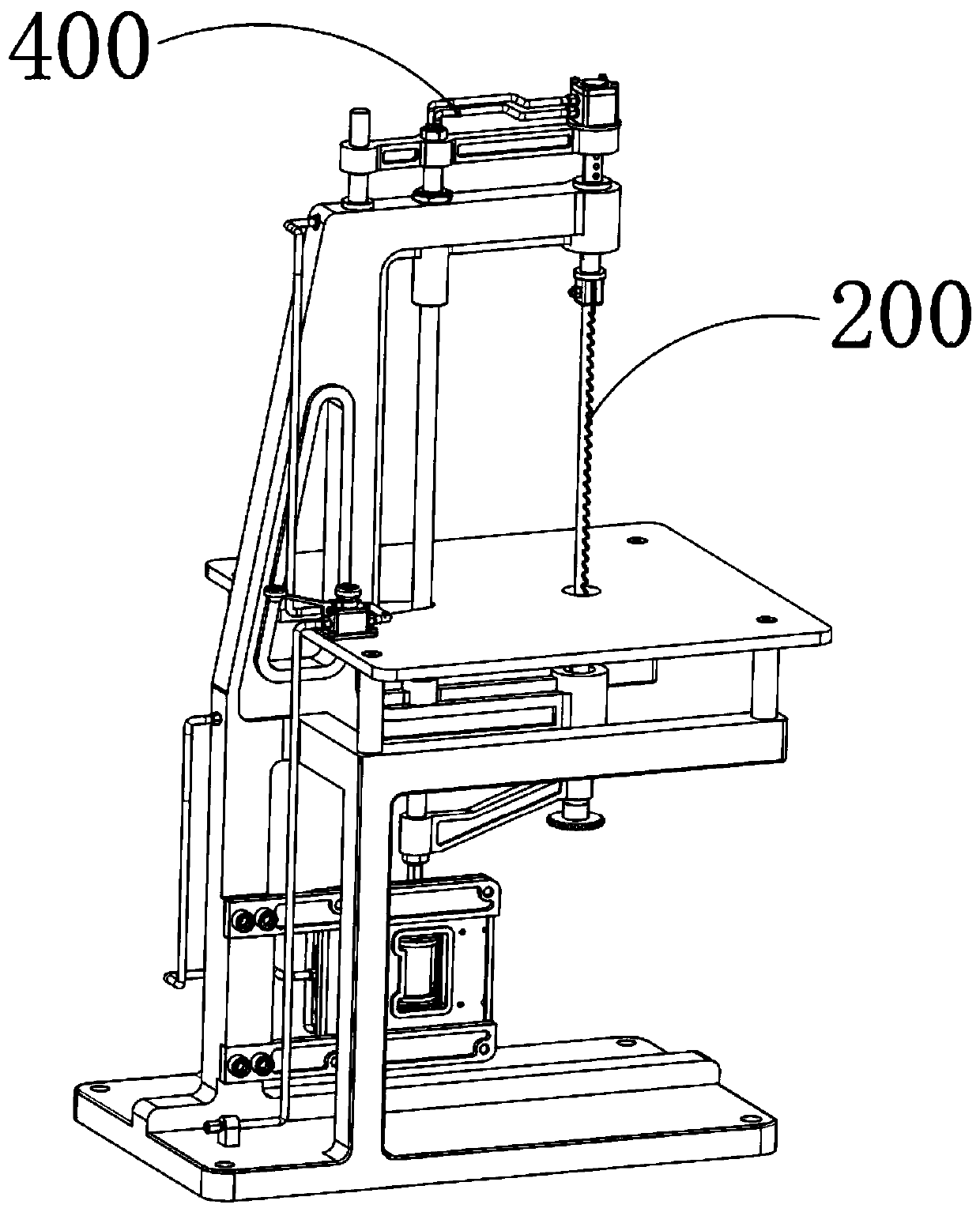
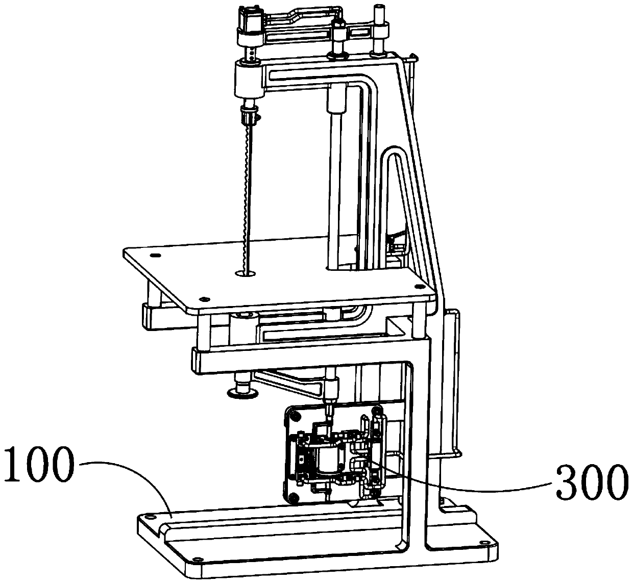
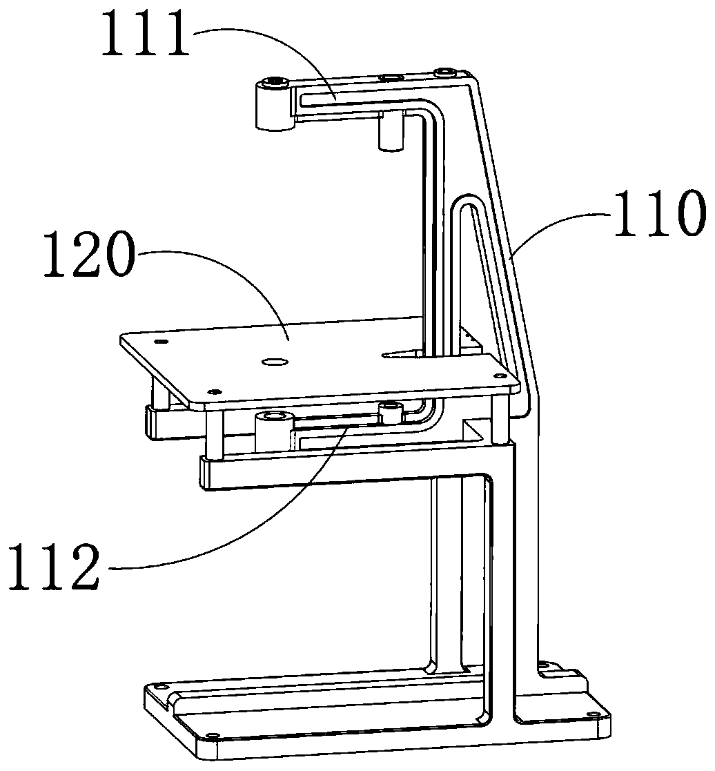
[0051] A multi-level protection pneumatic reciprocating saw, which includes a rectangular floor base 100, the top of the base 100 is provided with a support arm 110 extending vertically upwards, the top end of the support arm 110 is fixedly provided with a horizontally arranged upper arm 111, and the bottom end is fixedly provided with a The lower arm 112 arranged horizontally and the lower arm 112 is arranged correspondingly to the upper arm 111. A horizontal workbench 120 fixedly connected to the base 100 is arranged between the upper arm 111 and the lower arm 112 and the workbench 120 is arranged close to the lower arm 112. The upper arm 111 is connected to the lower arm 112. A saw body 200 is movable between the arms 112. The saw body 200 includes a saw blade 210 that is vertically arranged and moves through the workbench 120. The base 100 is provided with a pneumatic drive that drives the saw blade 210 to reciprocate up and down in the vertical direction. The device 300 is...


PUM


Abstract

The invention provides a multistage protection pneumatic reciprocating saw. The multistage protection pneumatic reciprocating saw comprises a rectangular floor base, wherein a supporting arm which vertically extends upwards is arranged at the top of the base, an upper arm which is horizontally arranged is fixedly arranged at the top end of the supporting arm, a lower arm which is horizontally arranged is fixedly arranged at the bottom end of the supporting arm, and the lower arm and the upper arm are arranged correspondingly; a horizontal working table fixedly connected with the base is arranged between the upper arm and the lower arm, and the working table is arranged close to the lower arm, and a saw body is movably arranged between the upper arm and the lower arm. The saw body comprisesa saw blade which is vertically arranged and movably penetrates through the working table, a pneumatic driving device which drives the saw blade to move up and down in the vertical direction is arranged in the base, an air supply protection device is in communication between the high-pressure air source and an input end of the pneumatic driving device and is used for controlling the on-off of high-pressure air, and the air supply protection device comprising an emergency stop switch and a broken saw protection mechanism.

Description

technical field [0001] The invention relates to a saw, in particular to a multi-level protection pneumatic reciprocating saw. Background technique [0002] Saw is one of the common tools in daily life. It is mainly used for cutting wood, etc. According to the classification of driving power, it can be roughly divided into two categories. One is manual saw, which mainly includes the saw body and The saw blade is composed of manually pulling the reciprocating motion of the saw body to drive the reciprocating motion of the saw blade to cut the wood, but it has obvious disadvantages, that is, time-consuming and labor-intensive, and the efficiency of cutting wood is low. The second is the electric saw. Invented by Andreas Steele in 1926, it greatly saves the time and manpower spent on cutting materials. It drives the saw blade to cycle through the motor to cut wood. The saw blade is generally made of tool steel. There are circular, strip and chain types, but there are also certa...

Claims


Application Information

Patent Timeline
Patent Type & Authority Patents(China)
IPC IPC(8): B23D51/16B23D51/18B23D59/00
CPCB23D51/166B23D51/18B23D59/00
Inventor 魏大平张勤
Owner 永康市亿科锯业有限公司
Why Eureka
Try Eureka