
Cabinet air conditioner indoor unit

A cabinet-type air conditioner and indoor unit technology, which is applied in air-conditioning systems, heating methods, space heating and ventilation, etc., can solve problems such as unsatisfactory heat transfer effects of evaporators, improve user experience, improve cleanliness, and reduce floating particle effect

Pending Publication Date: 2019-11-26
QINGDAO HAIER AIR CONDITIONER GENERAL CORP LTD +1
View PDF7 Cites 0 Cited by
  • Summary
  • Abstract
  • Description
  • Claims
  • Application Information

AI Technical Summary

Problems solved by technology

[0005] In order to solve the above-mentioned problems in the prior art, that is, to solve the problem of the unsatisfactory heat exchange effect of the evaporator of the existing cabinet-type air conditioner indoor unit, the present invention provides a cabinet-type air conditioner indoor unit, the cabinet-type air conditioner The indoor unit includes: a body, the body is provided with an air inlet and a first air outlet, the body is provided with a blower fan, an evaporator, a water tray and a sterilization and purification module, and the water tray is arranged on the Below the evaporator, the sterilization and purification module is arranged at the air inlet; the fresh air module is arranged under the body and connected to the body, and the fresh air module is provided with an air suction port and an exhaust The air suction port communicates with the outside through the pipeline, and the air exhaust port communicates with the air inlet; wherein, the evaporator includes a coil and fins arranged on the coil, and the coil The centerline of the center line is arranged in a spiral form from top to bottom around a vertical axis

Method used


Image

  • Cabinet air conditioner indoor unit
  • Cabinet air conditioner indoor unit
  • Cabinet air conditioner indoor unit

Examples


Embodiment 1

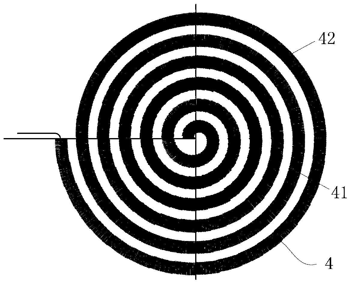
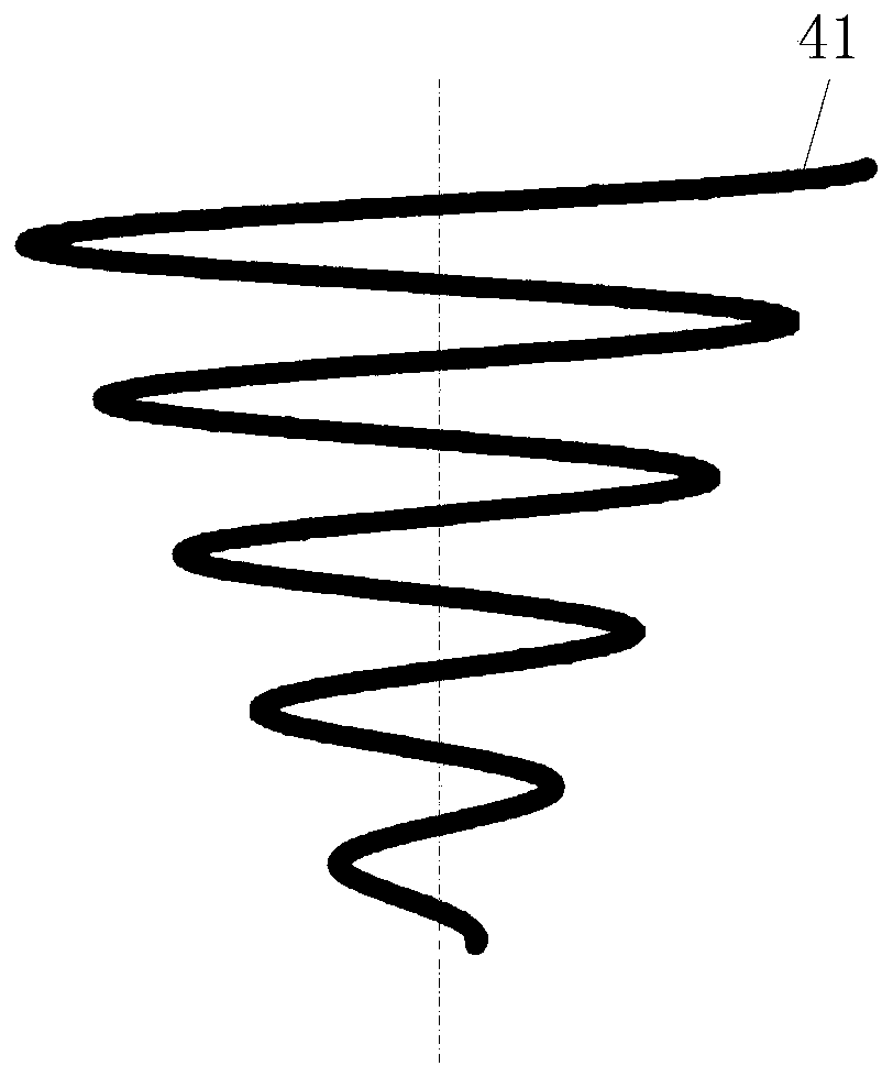
[0045] First refer to Figure 2A and Figure 2B , the evaporator of the present invention is described. in, Figure 2A It is a top view of the evaporator of the present invention; Figure 2B It is a front sectional view of the evaporator of the present invention.

[0046] like Figure 2A and Figure 2B As shown, in order to solve the problem of the unsatisfactory heat exchange effect of the evaporator of the existing cabinet air conditioner indoor unit, the first aspect of the present application provides an evaporator 4, the evaporator 4 includes a coil 41 and is arranged on the coil The fins 42 on the tube 41 , especially, the centerline of the coiled tube 41 are arranged in a spiral form from top to bottom around a vertical axis.

[0047] By setting the coil tube 41 of the evaporator 4 in a spiral shape from top to bottom around a vertical axis on the center line, when the evaporator 4 is installed in the indoor unit of the cabinet air conditioner, the refrigerant flo...

Embodiment 2

[0054] Refer below Figure 1 to Figure 6 , the first embodiment of the cabinet air conditioner indoor unit of the present invention will be described.

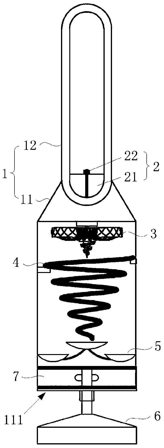
[0055] First refer to figure 1 , figure 1 It is a structural diagram of a cabinet-type air conditioner indoor unit in the first embodiment of the present invention. like figure 1 As shown, the present invention also provides a cabinet-type air conditioner indoor unit, the cabinet-type air conditioner indoor unit includes a body 1, and the body 1 is provided with an air inlet 111 and a first air outlet 123 (refer to Figure 3A ), a humidifying device 2 is provided at the first air outlet 123, and a sterilization and purification module 7, a water receiving tray 5, an evaporator 4, and an air blower 3 are arranged in sequence along the air flow direction in the body 1, and the water receiving tray 5 is arranged on the evaporator Below the device 4, the sterilization and purification module 7 is arranged at the air inlet 111....

Embodiment 3

[0078] Refer below Figure 7 to Figure 9C , to describe the second implementation manner of the cabinet air conditioner indoor unit of the present application.

[0079] First refer to Figure 7 and Figure 8 , the structure of the indoor unit of the cabinet air conditioner is described. in, Figure 7 It is a structural diagram of a cabinet-type air conditioner indoor unit in the second embodiment of the present invention; Figure 8 It is a structural diagram of the fresh air module of the present invention.

[0080] like Figure 7 and Figure 8 As shown, on the basis of the cabinet air conditioner indoor unit in any arrangement form described in Embodiment 2, the cabinet air conditioner indoor unit is also provided with a fresh air module 8, and the fresh air module 8 is arranged under the body 1 and connected to the body 1 , the fresh air module 8 is provided with an air suction port 811 and an air exhaust port 812, the air suction port 811 communicates with the outsid...


PUM


Abstract

The invention relates to the technical field of air conditioning, in particular to a cabinet air conditioner indoor unit. The cabinet air conditioner indoor unit aims at solving the problem that the heat exchange effect of an evaporator of an existing cabinet air conditioner indoor unit is not ideal. In order to solve the problem, the cabinet air conditioner indoor unit comprises a unit body and afresh air module. The unit body is provided with an air inlet and a first air outlet, and an air supply draught fan, an evaporator, a water collecting plate and a sterilizing and purifying module arearranged in the unit body. The water collecting plate is arranged below the evaporator, and the sterilizing and purifying module is arranged at the position of the air inlet. The fresh air module isarranged below the unit body and is connected with the unit body. The fresh air module is provided with an air suction opening and an exhaust opening, wherein the air suction opening communicates withthe outdoor part through a pipeline, and the exhaust opening communicates with the air inlet. The evaporator comprises a coil pipe and fins arranged on the coil pipe, and the center line of the coilpipe is arranged spirally around a vertical axis in a vortex shape from top to bottom.

Description

technical field [0001] The invention relates to the technical field of air conditioning, in particular to a cabinet type air conditioner indoor unit. Background technique [0002] As air conditioners are widely used in thousands of households, users have higher and higher requirements for the performance of air conditioners. Take the cabinet air conditioner as an example. Usually under the same conditions, the performance of the cabinet air conditioner depends on the heat exchange efficiency, and the heat exchange efficiency is directly related to the heat exchange area. The larger the heat exchange area, the higher the heat exchange efficiency. high. [0003] Usually, the structure and arrangement of the evaporator directly determine the size of the heat exchange area and the heat exchange efficiency. In existing cabinet-type air conditioners, the evaporator is usually placed obliquely inside the air conditioner casing or attached to the air inlet, and the coils are arran...

Claims


Application Information

Patent Timeline
IPC IPC(8): F24F1/005F24F1/0014F24F1/0063F24F1/0067F24F1/0073F24F1/0076F24F13/30F24F13/22
CPCF24F1/005F24F1/0014F24F1/0063F24F1/0067F24F1/0073F24F1/0076F24F13/30F24F13/222
Inventor 刘光朋史为品
Owner QINGDAO HAIER AIR CONDITIONER GENERAL CORP LTD
Learn More