
A pressure resistant sealing structure of imaging system

An imaging system and pressure-resistant sealing technology, which is applied to the components of the TV system, image communication, camera body, etc., can solve the problems that the pressure resistance is not as good as the spherical structure, the thickness of the material is large, and it is not light enough to achieve pressure resistance. Good performance, uniform stress distribution, and not easy to stress concentration

Active Publication Date: 2019-11-22
CHANGCHUN INST OF OPTICS FINE MECHANICS & PHYSICS CHINESE ACAD OF SCI
View PDF6 Cites 4 Cited by
  • Summary
  • Abstract
  • Description
  • Claims
  • Application Information

AI Technical Summary

Problems solved by technology

However, since the pressure resistance of the flat plate structure and cylindrical structure with the same caliber and thickness is far inferior to that of the spherical structure, the material required for this structure is thicker, heavier and not light enough

Method used


Image

  • A pressure resistant sealing structure of imaging system
  • A pressure resistant sealing structure of imaging system

Examples


Embodiment Construction

[0022] The following will clearly and completely describe the technical solutions in the embodiments of the present invention with reference to the accompanying drawings in the embodiments of the present invention. Obviously, the described embodiments are only some, not all, embodiments of the present invention. Based on the embodiments of the present invention, all other embodiments obtained by persons of ordinary skill in the art without making creative efforts belong to the protection scope of the present invention.

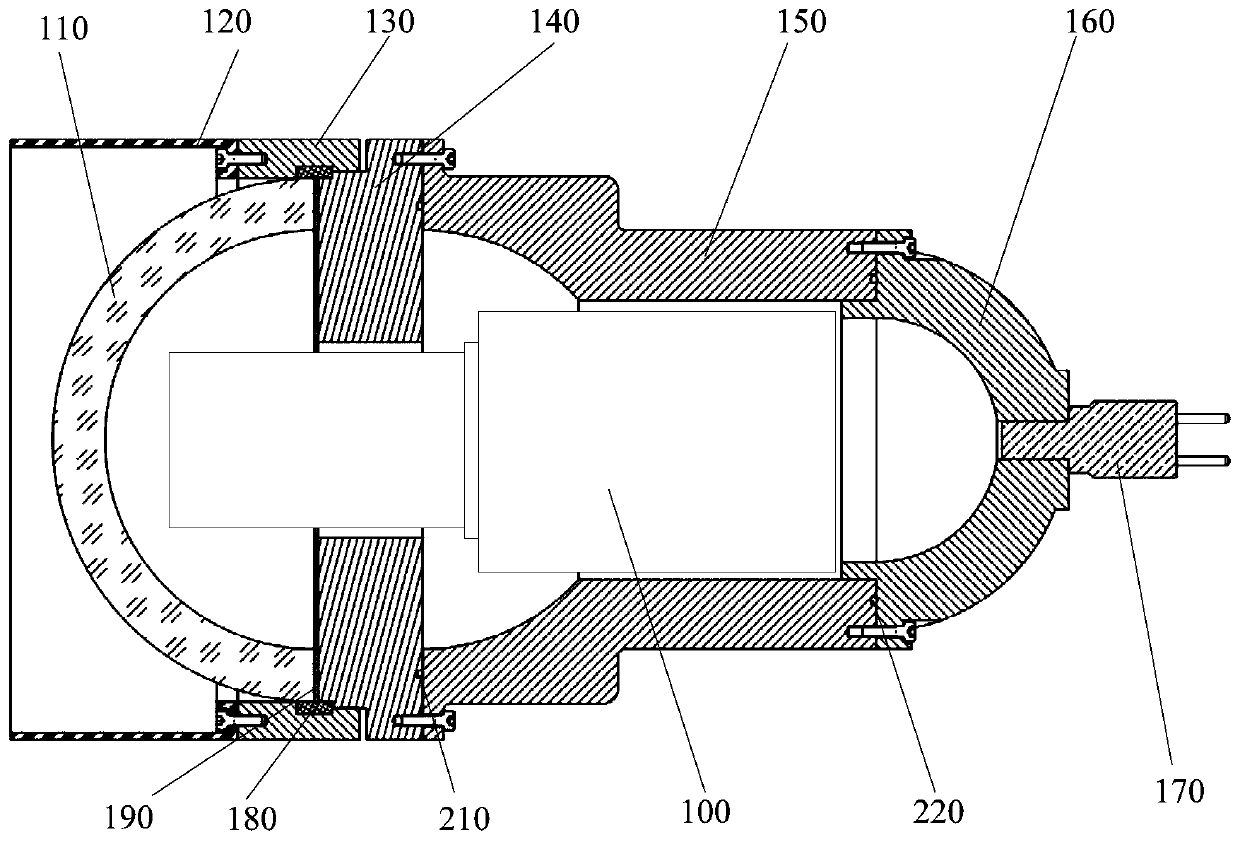
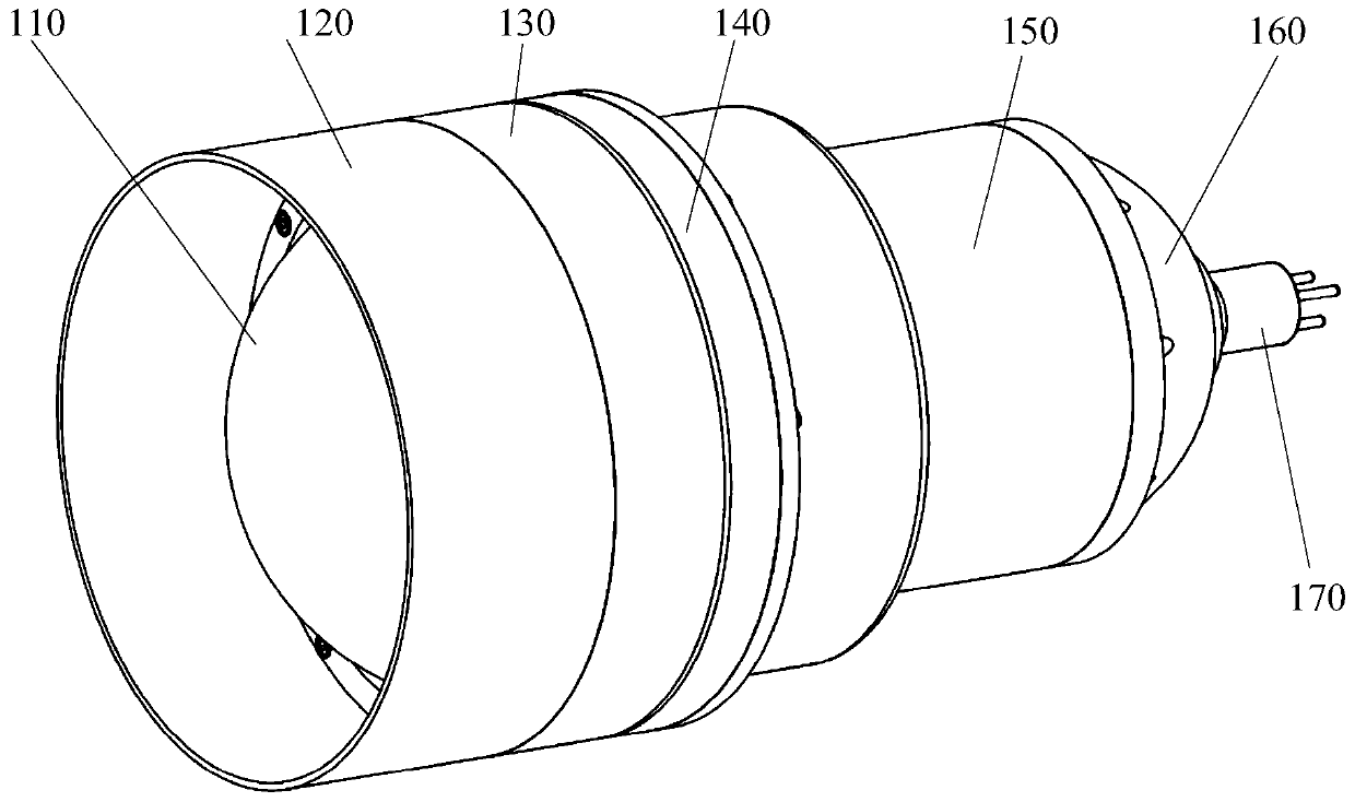
[0023] see figure 1 , is a schematic structural diagram of a pressure-resistant sealing structure of an imaging system provided in Embodiment 1 of the present invention, including: a hemispherical light-transmitting cover 110, a light-shielding cover 120, a sealing ring pressure ring 130, a light-transmitting cover base 140, and a pressure-resistant cylinder 150. Rear end cover 160 and electrical interface 170, the hemispherical light-transmitting cover 110 is...


PUM


Abstract

The invention provides a pressure-resistant sealing structure of an imaging system. The structure comprises a hemispherical light-transmitting cover, a light shield, a sealing ring pressing ring, a light-transmitting cover base, a pressure-resistant cylinder, a rear end cover and an electrical interface; according to the pressure-resistant sealing structure of the imaging system, the transparent ceramic is adopted as an optical window of the hemisphere light-transmitting cover, the pressure resistance is better, the main body structure is of a spherical structure, and sealing design is conducted according to the characteristics of the hemisphere structure, so the sealing performance is better; as the main body structure adopts the spherical structure, the stress distribution is uniform, the stress concentration is not easy to occur, and the pressure resistance and portability are realized.

Description

technical field [0001] The invention relates to the technical field of deep-sea imaging, in particular to a pressure-resistant sealing structure of an imaging system. Background technique [0002] With the depletion of land resources, human beings are increasingly marching into the deep sea. In the past 10 years, there have been more and more marine scientific expeditions and research activities in marine biology, marine mineral resources, marine ecological environment, marine environmental pollution investigation and control, marine geophysics, marine climate and atmosphere, marine chemistry, and marine geology. Frequently, deep-sea equipment is becoming more and more active in marine research, and its role is becoming more and more important. The collection, analysis, cultivation and research of deep-sea biological genes under the conditions of heat preservation and pressure preservation in the deep ocean will have an important impact on human science and life. [0003] ...

Claims


Application Information

Patent Timeline
IPC IPC(8): G03B17/08H04N5/225
CPCG03B17/08H04N23/51
Inventor 刘英杜杰王伟智周国红覃显鹏邢妍
Owner CHANGCHUN INST OF OPTICS FINE MECHANICS & PHYSICS CHINESE ACAD OF SCI
Learn More