
Radar speed measurement system and method based on Rydberg atom electromagnetic induction transparency effect

A technology of electromagnetically induced transparency and radar speed measurement, applied in radio wave measurement systems, radio wave reflection/re-radiation, measurement devices, etc. The effect of reduction, broad application prospects and scientific research value

Active Publication Date: 2019-11-22
QINGYUAN TIANZHIHENG SENSING TECH CO LTD
View PDF13 Cites 5 Cited by
  • Summary
  • Abstract
  • Description
  • Claims
  • Application Information

AI Technical Summary

Problems solved by technology

[0003] The inventor found in the research that the defect of the traditional technology is that the receiving antenna of the existing radar speed measurement system is usually made of metal, and the detection accuracy of the electromagnetic signal is limited. Due to various constraints such as size, shape, and working environment, 1mV / cm is the recognized minimum detection electric field strength
In addition, traditional radar speed measurement systems often require complex circuit connections and filter amplification processing, resulting in large thermal noise

Method used


Image

  • Radar speed measurement system and method based on Rydberg atom electromagnetic induction transparency effect
  • Radar speed measurement system and method based on Rydberg atom electromagnetic induction transparency effect
  • Radar speed measurement system and method based on Rydberg atom electromagnetic induction transparency effect

Examples


Embodiment Construction

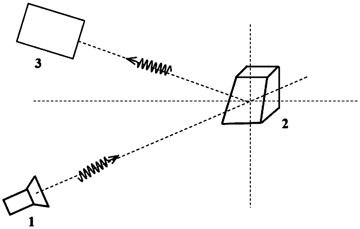
[0032] like figure 1 As shown, the radar speed measurement system based on the electromagnetically induced transparency effect of Rydberg atoms includes a transmitting antenna 1, a moving object 2 and an atomic receiving antenna 3, where:

[0033] Transmitting antenna 1 emits microwaves, which cause blue detuning due to Doppler frequency shift due to microwave scattering by moving objects 2;

[0034] The atom receiving antenna 3 receives the detuned microwave, and obtains the speed information of the moving object 2 therefrom.

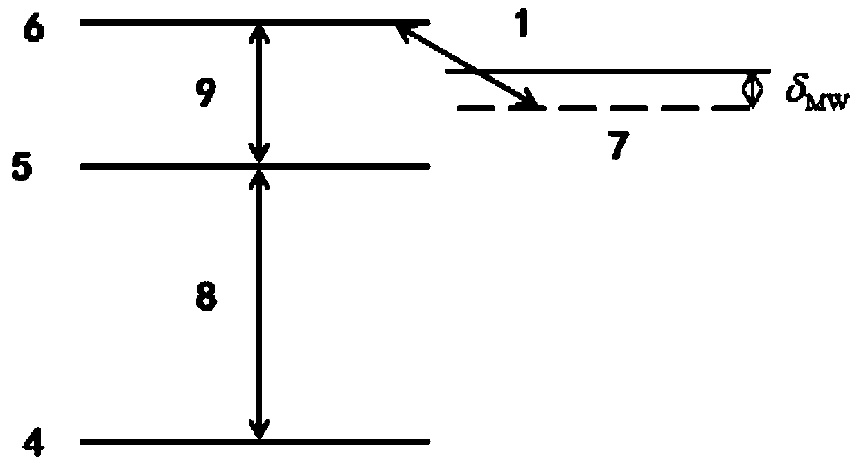
[0035] The atomic receiving antenna includes cesium bubbles, lasers and photodetectors. The cesium bubble provides cesium atom gas under the saturated vapor pressure at room temperature, and the cesium atom gas converts the amplitude measurement in the microwave band into the frequency measurement in the optical band in the Rydberg electromagnetically induced transparency effect. The laser generates probe light with a wavelength of 852nm and coupled ...


PUM


Abstract

The invention relates to a radar speed measurement system and method based on a Rydberg atom electromagnetic induction transparency effect. The system comprises a transmitting antenna and an atom receiving antenna used for replacing a traditional metal receiving antenna. The transmitting antenna transmits microwaves, and the microwaves are scattered by a moving object to be subjected to speed measurement to generate Doppler frequency shift to cause detuning, so that speed information of the moving object to be subjected to speed measurement is carried; the atom receiving antenna provides alkali metal atoms and generates an EIT effect in a Rydberg state, and an EIT transmission peak appears; and the atom receiving antenna is used for receiving the detuned microwaves, so that the EIT transmission peak is split, and the speed information of the moving object to be subjected to speed measurement is obtained according to the split distance of the two peaks. According to the invention, the detection sensitivity can be improved, the frequency response range is expanded, the influence of thermal noise is avoided, and miniaturization and integration are easy.

Description

technical field [0001] The invention relates to the technical field of radar speed measurement, in particular to a radar speed measurement system and method based on the electromagnetically induced transparency effect of Rydberg atoms. Background technique [0002] At present, radar has been widely used in the field of speed measurement. Radar speed measurement mainly uses the Doppler effect: when the target is close to the radar antenna, the frequency of the reflected signal will be higher than the frequency of the transmitter; The frequency will be lower than the transmitter frequency. The relative speed between the target and the radar can be calculated by changing the value of the frequency. [0003] The inventor found in the research that the defect of the traditional technology is: the receiving antenna of the existing radar speed measurement system is usually made of metal, and the detection accuracy of the electromagnetic signal is subject to various constraints suc...

Claims


Application Information

Patent Timeline
Patent Type & Authority Applications(China)
IPC IPC(8): G01S13/58G01S7/02
CPCG01S13/58G01S7/02
Inventor 梁洁廖开宇张新定颜辉
Owner QINGYUAN TIANZHIHENG SENSING TECH CO LTD
Learn More