Eureka AIR delivers breakthrough ideas for toughest innovation challenges, trusted by R&D personnel around the world.

Folding emergency bridge and using method

A folding and bridge technology, applied in bridges, bridge forms, portable bridges, etc., can solve the problems that large-scale hoisting equipment is difficult to reach the site, cannot be considered as an object, and takes a long time to save space, achieve high automation, The effect of preventing overturning

Inactive Publication Date: 2019-11-22
CHINA THREE GORGES UNIV
View PDF5 Cites 12 Cited by
  • Summary
  • Abstract
  • Description
  • Claims
  • Application Information

AI Technical Summary

Problems solved by technology

The former requires the use of hoisting equipment such as large cranes, but when a disaster occurs, it is difficult for large hoisting equipment to reach the scene; while the latter requires the deployment of military equipment, the declaration process takes a long time in emergency situations, and the station may be far away from the disaster site. cannot be considered

Method used


Image

  • Folding emergency bridge and using method
  • Folding emergency bridge and using method
  • Folding emergency bridge and using method

Examples


Embodiment 1

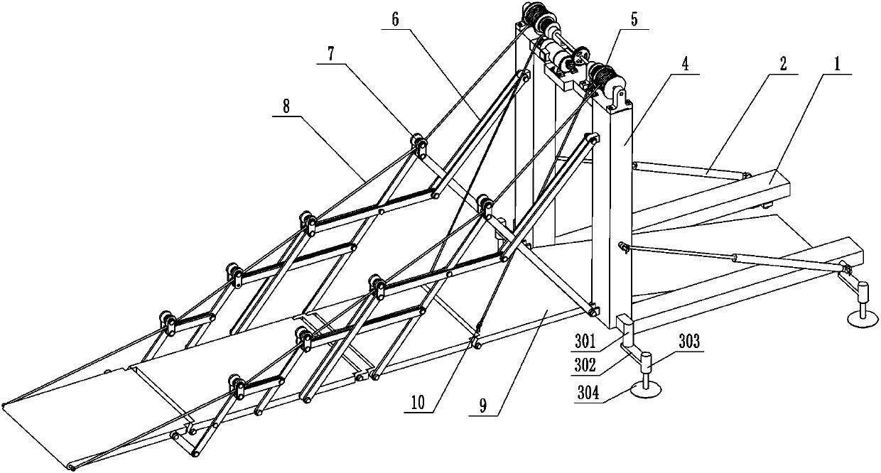
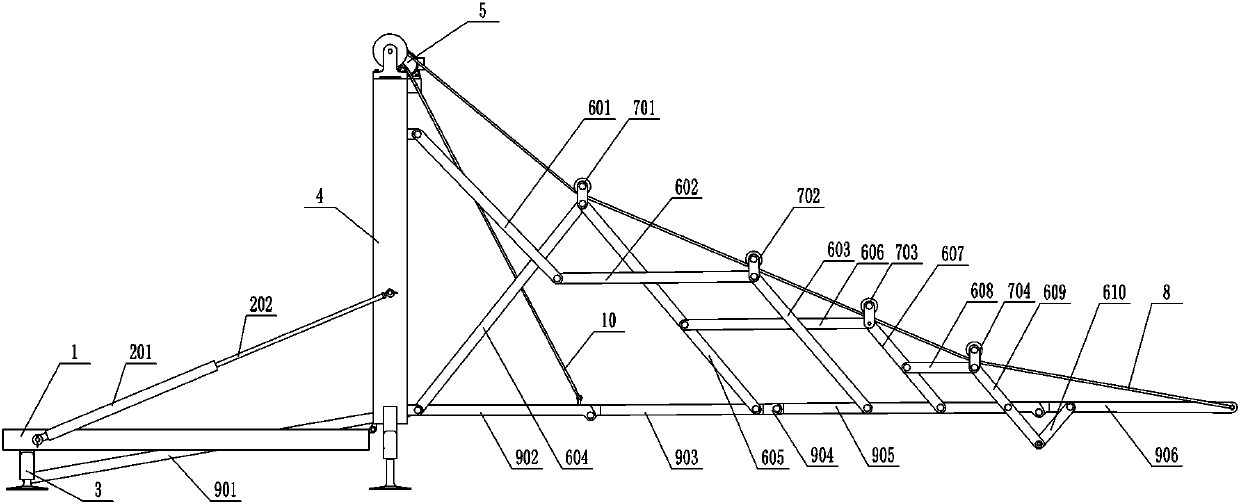
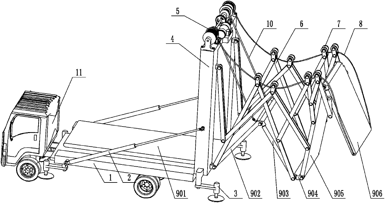
[0044] Such as Figure 1-6 , a folding emergency bridge, which includes a bridge main part, the bridge main part includes a base 1 supported on the ground, and a column 4 is hinged on the base 1; Drive the hydraulic cylinder 2 to rotate, and the other side wall of the column 4 is hinged with a pin shaft to have a foldable bridge deck surface 9, and the bridge deck surface 9 and the side wall of the column 4 are symmetrically arranged The lateral folding frame 6 is hingedly connected, and a wire rope system 5 for providing traction is symmetrically fixed on the top of the column 4, and one of the winding drums of the wire rope system 5 is fixed on the folding frame 6 through the first drum wire rope 8. A plurality of guide wheels 7 on the top are matched, and their ends are connected to the end of the bridge deck surface 9. The other winding drum of the wire rope system 5 is connected to the first section of the bridge deck surface 9 through the second drum wire rope 10. conne...

Embodiment 2

[0057] The using method of a kind of folding emergency bridge described in any one, it comprises the following steps:

[0058] Step1: The transport vehicle 11 carrying the folding bridge is driven to the side of the river where the bridge needs to be erected, and the rear of the car is parked facing the river;

[0059] Step2: Start the hydraulic cylinder 2, and erect the bridge body through the hydraulic cylinder 2. When the column 4 is perpendicular to the ground, the hydraulic cylinder stops working and maintains this state;

[0060] Step3: Unfold all four movable outriggers 3, and activate the outrigger hydraulic cylinder to prop up the entire slow bridge. One end of the bridge deck surface 901 lands;

[0061] Step3: Start the deceleration motor 508, and transmit the rotation movement to the first roller 502 and the second roller 503 through the gear, and slowly stretch the wire rope, and the folding bridge body will unfold forward by its own gravity until the entire bridg...


PUM


Abstract

The invention discloses a folding emergency bridge and a using method thereof. The folding emergency bridge comprises a bridge main body part, the bridge main body part comprises a base supported on the ground, and a stand column is hinged to the base. A hydraulic cylinder used for driving the stand column and the base to rotate is installed between the stand column and the base. A plurality of sections of foldable bridge plate surfaces are hinged to the other side wall of the stand column through pin shafts; and the bridge plate faces and the side wall of the stand column are connected in a hinged mode through lateral folding frameworks which are symmetrically arranged. Steel wire rope systems used for providing traction force are symmetrically fixed to the top of the stand column. One ofwinding drums of the steel wire rope system is matched with a plurality of guide wheels fixed to the top of the folding framework through a first roller steel wire rope, the tail end of the winding drum is connected to the tail end of the bridge deck, and the other winding drum of the steel wire rope system is connected with the first-section bridge deck of the bridge deck through a second rollersteel wire rope. The bridge is light in self weight and convenient to transport by various operation vehicles; and the connecting rod is flexible in structural design, high in erecting and retractingoperation efficiency, low in requirement for an operation site and high in automation degree.

Description

technical field [0001] The invention relates to an emergency bridge, in particular to a foldable emergency bridge, which belongs to the field of bridge construction. Background technique [0002] A bridge is a building erected on rivers, lakes and seas for pedestrians and vehicles to cross the water surface. It usually consists of a superstructure, a substructure, a support and ancillary structures. The main structure; the substructure includes the bridge abutment, bridge piers and foundation; the support is the force transmission device set at the supporting place between the bridge span structure and the bridge piers or the bridge abutment; the auxiliary structures refer to the bridge head buttress, conical revetment, revetment, diversion engineering etc. [0003] Bridges play an important role in daily travel and life, but in the event of natural disasters such as strong earthquakes, landslides, mountain torrents and mudslides, bridges are prone to collapse, causing traf...

Claims


Application Information

Patent Timeline
Patent Type & Authority Applications(China)
IPC IPC(8): E01D15/00E01D15/12
CPCE01D15/00E01D15/12E01D15/124
Inventor 田启华舒正涛周祥曼
Owner CHINA THREE GORGES UNIV
Why Eureka
Eureka Blog
Learn More