
Expandable USB data terminal for time & attendance and data collection applications

Inactive Publication Date: 2009-03-05
LATHEM TIME CORP
View PDF4 Cites 16 Cited by
  • Summary
  • Abstract
  • Description
  • Claims
  • Application Information

AI Technical Summary

Benefits of technology

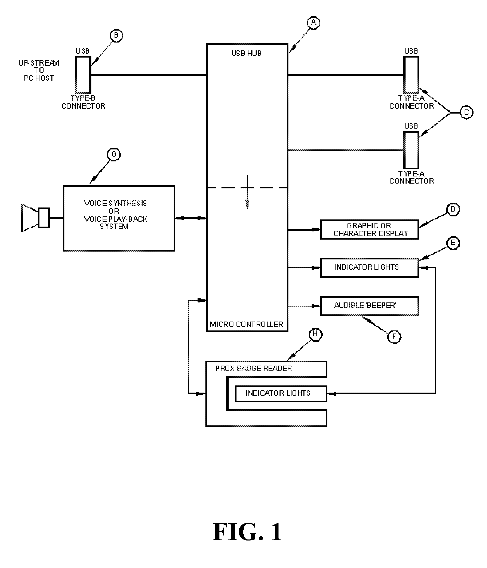
[0026]The technology described herein employs an integrated USB hub to provide a low-cost, universal means of feature expansion that may be field-enhanced without the need for special skills or tools.
[0035]In one embodiment of the technology described herein a Time & Attendance Transaction Terminal that incorporates a Badge / Token Reader and a Character display capable of showing Alpha and / or Numeric Characters / Digits is connected either to a Host Computer or through a Hub accoriding to the USB Connectivity Specification, and which derives its operating power from the Host Computer or a USB Hub through the USB Cable. The single USB Cable carries both transaction data and operating power for the Terminal, and relieves the requirement of having batteries or a separate source cable to bring operating power to the Terminal.

Problems solved by technology

Multiple problems exists with current time and attendance devices.
In some situations, the designer will anticipate the need for future expansion but because the nature of the future expansion requirements is unknown at the time the design will be of a general purpose serial or parallel type; often having either more capability than will be ultimately needed, which increases cost, or insufficient capability to suit a future requirement which renders the facility useless for that purpose.
This approach has two inherent problems:1. having to predetermine what future expansion options may be required2. an additional production cost of the standard unit to support the program, memory and physical connection to these options.
When employees utilize a T&A (Time & Attendance) terminal, they are often in a great hurry to either start or terminate their work day.
As a result, they are apt to be too abrupt in completing their transactions and not take heed of simple auditory, e.g., beeps, or visual queues, e.g., colored lights, indicating the completion status of the transaction.
This is a particular problem if the intended transaction is rejected by the terminal, but the employee is unaware of this condition.
As a result, the transaction is not properly recorded and the employee's time record may be incorrect for proper payroll calculation, or may result in an unjustified tardiness report.
In addition, terminals that rely only upon simple auditory or visual queues may be difficult, inappropriate for, or unusable by, visually impaired personnel.
Designers of T&A and other data collection terminals have incorporated coded audio signals, e.g. coded beeps, colored lights, e.g. green for “Yes”; red for “No”, and expensive character and / or graphic displays to provide user information and prompting.
None of these solutions have reduced cost and complexity while expanding aesthetic design freedom by integrating these features using controlled, illuminated indicia.
While designers have attempted to anticipate the need for future expansion, because the nature of the future expansion requirements is unknown at the time, the design will be of a general purpose serial or parallel type; often having either more capability than will be ultimately needed (increasing cost), or insufficient capability to suit the future requirement (rendering the facility useless).
Until the integration of a USB hub component with a general purpose microcontroller, it would not have been cost effective to include a universal expansion hub as a standard feature.
A further problem is that Time & Attendance Transaction Terminals that are not Battery Operated require two connecting cables, one for power and another for data transmission; or they may require a unique cable that combines the data-carrying wires and the power-carrying wires to be enclosed within a single cable jacket, but which split-out the two functions into separate connectors to mate with standard sources and destinations; as if there were two cable assemblies.
Not only does this configuration represent a cost burden to terminal manufacturers and cable installers, but this duplicity of cables creates an unattractive installation of the Terminal upon the table or wall where the terminal is to be installed.
While these patents, published patent applications and other previous methods have attempted to solve the problems that they addressed, none have utilized or disclosed an integrated USB hub and microcontroller, as does embodiments of the technology described herein.

Method used


Image

  • Expandable USB data terminal for time & attendance and data collection applications
  • Expandable USB data terminal for time & attendance and data collection applications
  • Expandable USB data terminal for time & attendance and data collection applications

Examples


Embodiment Construction

[0055]The technology described herein will now be described in detail with reference to a few preferred embodiments thereof as illustrated in the accompanying drawings. In the following description, numerous specific details are set forth in order to provide a thorough understanding of the technology described herein. It will be apparent, however, to one skilled in the art, that the technology described herein may be practiced without some or all of these specific details. In other instances, well known operations have not been described in detail so not to unnecessarily obscure the technology described herein.

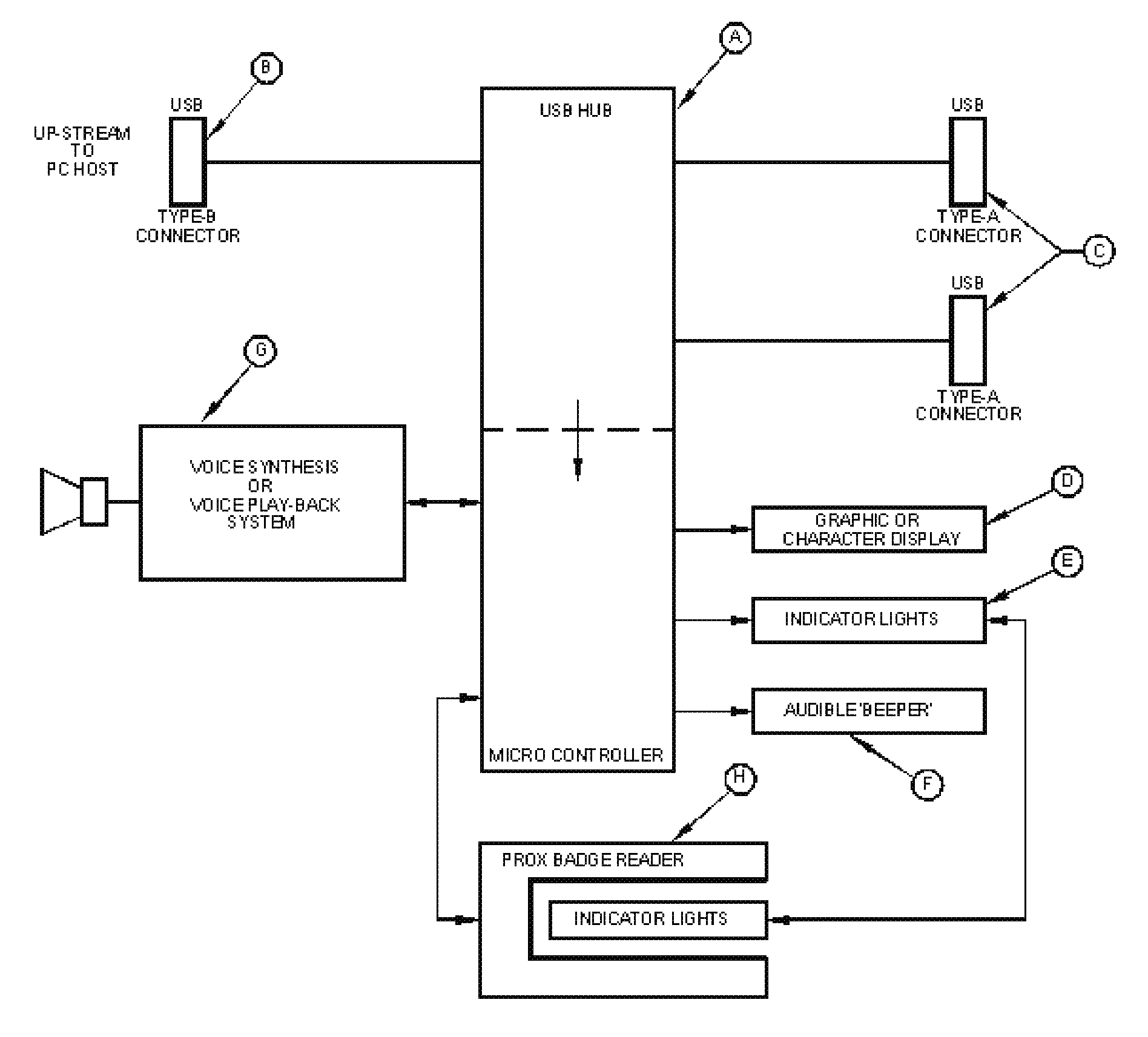
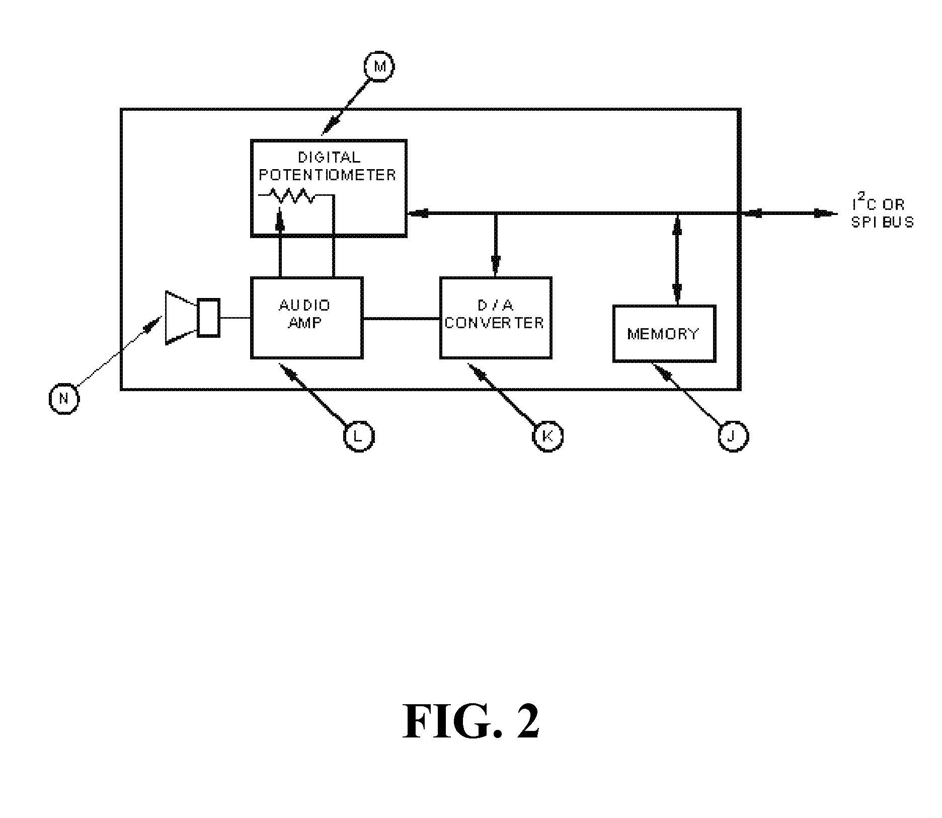
[0056]Referring now to FIG. 1 through FIG. 5 as part of the data collection terminal, a controlling microprocessor / microcontroller is integrated with a USB hub to provide a simple and low-cost means of future functional expansion through the attachment of functionally related peripheral devices. A currently available component that fulfills this requirement is the Texas Instru...


PUM


Abstract

A time and attendance device having an integrated USB hub and microcontroller is provided. An automated voice feature is provided that is controlled in response to user parameters. Also provided are a single target area having attention-getting illumination, proximity reader positioning, and transaction status indicators.

Description

[0001]This application claims the benefit of U.S. Provisional Application No. 60 / 88,055, filed Feb. 2, 2007.FIELD OF THE INVENTION[0002]The technology described herein relates to the field of time and attendance devices and other data collection devices.BACKGROUND OF THE INVENTION[0003]Multiple problems exists with current time and attendance devices.[0004]In most situations data collection terminals, e.g., a time and attendance device, are designed to accomplish a specific task and all components needed to execute those tasks are included within the design. Providing circuitry and connectors for future expansion is often eschewed by the designer, primarily to minimize manufacturing costs. In some situations, the designer will anticipate the need for future expansion but because the nature of the future expansion requirements is unknown at the time the design will be of a general purpose serial or parallel type; often having either more capability than will be ultimately needed, whi...

Claims


Application Information

Patent Timeline
IPC IPC(8): G04B47/00
CPCG07C1/10
Inventor POTASH, ELLERY W.
Owner LATHEM TIME CORP
Learn More