Centring platform of large machine coupling

A coupling and machine technology, applied in metal processing, workpiece clamping devices, metal processing equipment, etc., can solve the problems of high resistance, time-consuming and labor-intensive, and high requirements on moderateness, so as to eliminate sliding friction and save energy. The effect of high manpower and versatility

Active Publication Date: 2019-11-22
泰安泰山科技有限公司
View PDF10 Cites 0 Cited by
  • Summary
  • Abstract
  • Description
  • Claims
  • Application Information

AI Technical Summary

Problems solved by technology

[0004] Rigid couplings have high requirements on the alignment of the two connected shafts. In the prior art, the traditional dial gauge marking method is still used for centering, and at least two dial gauges are used to align at least two dial gauges. The meter is tied to the machine shaft, and the head of the meter is pointed at the end face of the motor shaft and the cylindrical surface, and then the machine shaft is manually rotated to measure the end face and radial runout of the motor shaft. The connection is cumbersome, and it is necessary to choose a suitable installation for different shaft diameters. structure, when the machine shaft is turned manually, the resistance may be large, time-consuming and labor-intensive, and the dial gauge head slides over the motor shaft, and the head is likely to be damaged

Method used


Image

  • Centring platform of large machine coupling
  • Centring platform of large machine coupling
  • Centring platform of large machine coupling

Examples


Embodiment Construction

[0035] The following will clearly and completely describe the technical solutions in the embodiments of the present invention with reference to the accompanying drawings in the embodiments of the present invention. Obviously, the described embodiments are only some, not all, embodiments of the present invention. Based on the embodiments of the present invention, all other embodiments obtained by persons of ordinary skill in the art without making creative efforts belong to the protection scope of the present invention.

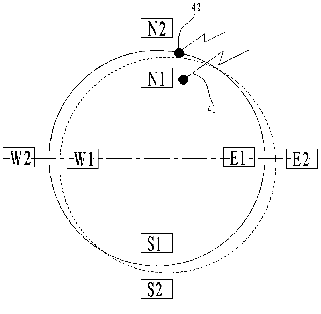
[0036] Such as Figure 1~5 As shown, a large-scale machine coupling centering platform is used for centering the machine shaft 81 and the motor shaft 82. The machine coupling centering platform includes a V-port block 1, an intermediate column 2, and a first dial gauge 41 and the second dial indicator 42, there are two V-port blocks 1 in total, and the V-port block 1 includes a V-shaped part 11 and an end plate 13. There are clamping holes 12 for two V-shaped...


PUM


Abstract

The invention discloses a centring platform of a large machine coupling. The centring platform is used for centring a machine shaft and a motor shaft. The centring platform of the machine coupling comprises V opening blocks, a middle column, first dial indicators and a second dial indicator. The total number of the V opening blocks is two. Each V opening block comprises a V-shaped portion and an end plate. Each end plate is arranged on the end face of one side of the corresponding V-shaped portion. Butt clamp holes used for combining mounting of the two V opening blocks are formed in the two sides of the V-shaped portions. The end face of one side of the middle column and the end faces of the sides, deviating from the V-shaped portions, of the end plates are connected through fasteners. The axis of the middle column coincides with the butt clamp center line of the V-shaped faces of the two V-shaped portions. The first dial indicators and the second dial indicator are connected to the middle column. The V opening blocks, the middle column, the first dial indicators and the second dial indicator are arranged on the machine shaft, the first dial indicators rotate along with the middlecolumn to measure the end face beating degree of the motor shaft, and the second dial indicator rotates along with the middle column to measure the radial beating degree of the motor shaft.

Description

technical field [0001] The invention relates to the field of coupling centering, in particular to a large machine coupling centering platform. Background technique [0002] Machines require power, often provided by electric motors. The connection between the machine shaft and the motor shaft is usually done through a coupling. [0003] For motors installed on horizontal feet, it is necessary to adjust the alignment with the machine shaft, otherwise, if the coaxiality tolerance between the motor shaft and the machine shaft is too large, it is not conducive to the normal operation of the coupling. Couplings are divided into flexible couplings and rigid couplings. Flexible couplings can buffer a large part of misalignment, but when the machine load is large and the torque is large, its carrying capacity is not as good as that of rigid couplings. , so when the transmission accuracy is high, the load is stable, and the high speed is high, more rigid couplings are used. [0004...

Claims


Application Information

Patent Timeline
IPC IPC(8): B23P19/10
CPCB25B11/00
Inventor 吕俊杰
Owner 泰安泰山科技有限公司
Why Eureka
Try Eureka