
Lifting-drawing pay-off rack

A pay-off stand and pull-up technology, applied in chemical instruments and methods, cleaning methods and utensils, cleaning methods using tools, etc., can solve the problems of wasted space, reduced wire processing quality, wire surface wear, etc. Wire quality, improve production efficiency, avoid the effect of wiring operations

Pending Publication Date: 2019-11-22
DEZHOU HENGYUAN WELDING MATERIAL
View PDF0 Cites 0 Cited by
  • Summary
  • Abstract
  • Description
  • Claims
  • Application Information

AI Technical Summary

Problems solved by technology

At present, the pay-off equipment such as the duckbill pay-off rack used by most wire rod production enterprises is mostly simple in structure. During production, the wire is sent out from the pay-off rack by the traction motor. , if the traction motor cannot be stopped in time, the wire will continue to be pulled by the traction motor, causing the wire to be forcibly pulled, or even broken
When this happens, the operator has to stop and rewire, which takes a long time and reduces the production efficiency of the entire production line
Secondly, when the traditional pay-off equipment is in use, there are many friction points between the wire rod, the pay-off frame and the ground, which not only produces considerable noise and vibration, but also causes serious wear on the wire rod surface, which affects the subsequent process and reduces the processing quality of the wire rod.
Thirdly, when the traditional pay-off equipment is used, a large area of ​​the wire is exposed in the workshop, and the horizontal footprint is large, which not only wastes space, but also poses a threat to the personal safety of the operator, with a low safety factor
[0003] Although the pay-off equipment provided by the prior art has solved some of the above-mentioned problems, it cannot completely solve the above-mentioned technical problems.

Method used


Image

  • Lifting-drawing pay-off rack
  • Lifting-drawing pay-off rack
  • Lifting-drawing pay-off rack

Examples


Embodiment Construction

[0051] In order to explain the overall concept of the present application more clearly, the following detailed description will be given by way of examples in combination with the accompanying drawings.

[0052] In order to understand the above-mentioned purpose, features and advantages of the present application more clearly, the present application will be further described in detail below in conjunction with the accompanying drawings and specific embodiments. It should be noted that, in the case of no conflict, the embodiments of the present application and the features in the embodiments can be combined with each other.

[0053] In the following description, many specific details are set forth in order to fully understand the present application, but the present application can also be implemented in other ways different from those described here, therefore, the protection scope of the present application is not limited by the specific details disclosed below. EXAMPLE LIMI...


PUM


Abstract

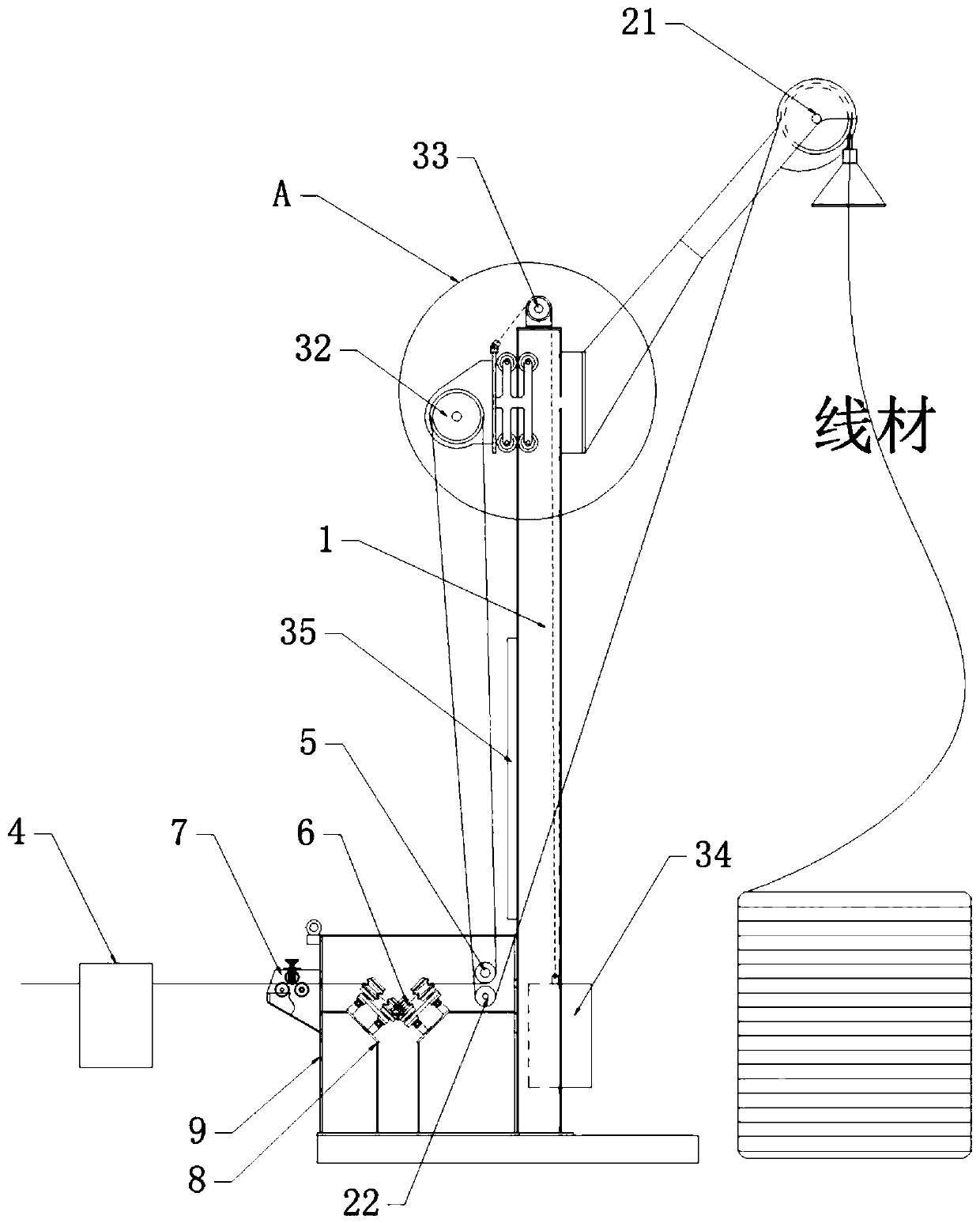
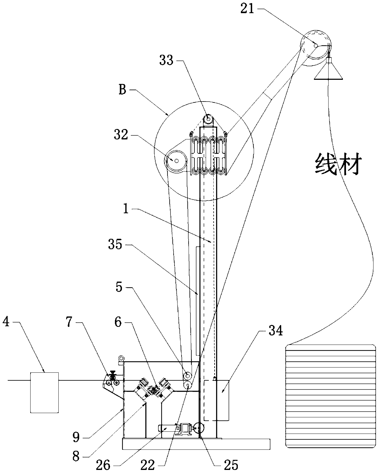
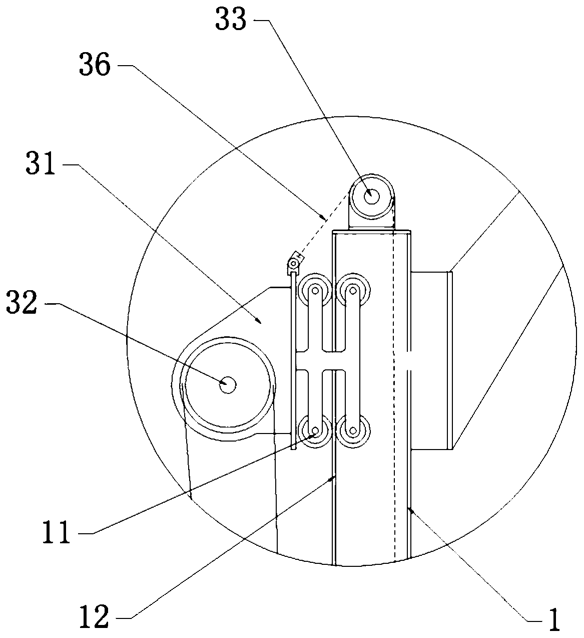
The application discloses a lifting-drawing pay-off rack and belongs to the technical field of wire production devices. The pay-off rack comprises a pay-off mechanism, a buffer mechanism and a supportframe, wherein the pay-off mechanism comprises a first pay-off guide wheel and a second pay-off guide wheel; the buffer mechanism comprises a first fixed pulley, a buffer guide wheel, a counterweightblock, a displacement sensor and a first lifting rope; the first fixed pulley is mounted on the support frame; the buffer guide wheel is mounted on a buffer-guide-wheel mounting base; and the first lifting rope is connected to the buffer-guide-wheel mounting base and the counterweight block. The lifting-drawing pay-off rack can untie a knot without overdrawing a wire, when the wire is slightly knotted due to a mess; and when the wire is seriously knotted, the lifting-drawing pay-off rack can stop paying off automatically to prevent the wire from being drawn apart, thereby avoiding unnecessarywire connection and increasing the production efficiency.

Description

technical field [0001] The application relates to a pull-type pay-off frame, which belongs to the field of wire rod production equipment. Background technique [0002] In the process of wire rod processing, it needs to go through multiple processes, such as wire laying, shelling, drawing, etc. At present, the pay-off equipment such as the duckbill pay-off rack used by most wire rod production enterprises is mostly simple in structure. During production, the wire is sent out from the pay-off rack by the traction motor. , if the traction motor cannot be stopped in time, the wire will continue to be pulled by the traction motor, causing the wire to be forcibly pulled, or even broken. When this happens, the operator has to stop and rewire, which takes a long time and reduces the production efficiency of the entire production line. Secondly, when using traditional pay-off equipment, there are many friction points between the wire and the pay-off frame and the ground, which not ...

Claims


Application Information

Patent Timeline
IPC IPC(8): B21C47/18B21C47/26B08B1/02B08B1/00
CPCB21C47/18B21C47/26B08B1/10B08B1/20
Inventor 薛建文李进詹玉萍
Owner DEZHOU HENGYUAN WELDING MATERIAL
Learn More