
Constant calibration method for differential absorption laser radar system

A technology of laser radar and system constants, applied in radio wave measurement systems, instruments, measuring devices, etc., can solve problems such as inversion error, complexity, and differential absorption laser radar inversion of target gas concentration errors, etc., to reduce inversion Error, the effect of improving data reliability

Active Publication Date: 2019-11-19
NANJING UNIV OF INFORMATION SCI & TECH
View PDF5 Cites 5 Cited by
  • Summary
  • Abstract
  • Description
  • Claims
  • Application Information

AI Technical Summary

Problems solved by technology

The light source of the differential absorption lidar system generally adopts the method of one lidar emitting two laser beams alternately or two lasers emitting two laser beams at the same time, and space detection also requires the use of three-dimensional turntables and other equipment, which is more complicated than other systems
Due to the complex optical path characteristics and the different wavelengths of the two laser beams of the differential absorption lidar, the initial energy of the on-wavelength and off-wavelength lasers is often different in actual detection, and the on and off laser beams are in actual detection. Beam combination may not be able to achieve complete coincidence, especially when detecting in invisible bands such as ultraviolet and infrared, because the laser is invisible, it is difficult to guarantee the quality of beam combination, which will make the differential absorption lidar inversion The concentration of the target gas causes a certain error. For those laser radars with a large energy difference between the on wavelength and the off wavelength, it will directly lead to an error in the retrieval

Method used


Image

  • Constant calibration method for differential absorption laser radar system
  • Constant calibration method for differential absorption laser radar system
  • Constant calibration method for differential absorption laser radar system

Examples


Embodiment Construction

[0022] The present invention will be described in further detail below in conjunction with the accompanying drawings.

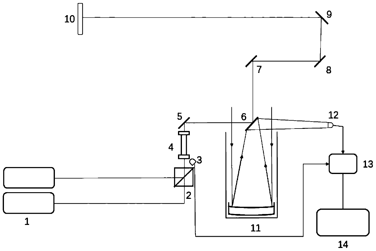
[0023] The present invention takes a set of general differential absorption laser radar system as an example, the laser radar system mainly includes a laser radar transmitting system, a laser radar receiving system and a main control system; wherein, the laser radar transmitting system includes a laser 1, a beam combiner 2, a One 45° full mirror 5, the second 45° full mirror 6, the third 45° full mirror 7, the fourth 45° full mirror 8, the fifth 45° full mirror 9, and the third 45° full mirror Reflective mirror 7, the fourth 45 ° full reflective mirror 8, the fifth 45 ° full reflective mirror 9 constitute a three-dimensional turntable and hard target 10; the lidar receiving system includes a cow anti telescope 11, the first photodetector 3, the second Photodetector 12 and signal acquisition card 13; Main control system uses industrial computer 14 to be connec...


PUM


Abstract

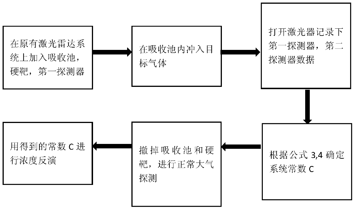
The invention relates to a constant calibration method for a differential absorption laser radar system and belongs to the technical field of laser radar detection. The method comprises the followingsteps that: (1) a first photoelectric detector, an absorption cell and a hard target are respectively placed at the emergent laser of the system; the position of the absorption cell is adjusted, the first photoelectric detector is arranged at the front end of the absorption cell and is used for signal monitoring and initial ON and OFF energy monitoring; (2) the absorption cell is vacuumized through a vacuum pump, and then is filled with a target gas of which the standard concentration is 20000 ppm, and pressure intensity in the absorption cell is recorded; (3) a laser is switched on, and ON and OFF signals detected by the first photoelectric detector and a second photoelectric detector are recorded through by a signal acquisition card; and (3) the constants of the radar system are determined according to acquired data, the absorption cell and the hard target are removed, normal atmospheric detection is performed, an improved inversion formula is adopted to perform normal gas concentration detection. With the method of the invention adopted, the initial energy of laser is monitored; laser states are recorded in real time; and data reliability is improved.

Description

technical field [0001] The invention relates to a method for calibrating differential absorption laser radar system constants, belonging to the technical field of laser radar detection. Background technique [0002] As an important tool for monitoring environmental pollutants, lidar has the advantages of strong anti-interference ability, high spatial resolution, high detection sensitivity, and long measurement optical path. It is widely used in the detection of aerosols, ozone, and various pollutant gases in the atmosphere. . As a kind of laser radar, differential absorption lidar is a new technology in the field of environmental monitoring in recent years, and has been widely used in the detection of the concentration of pollutant gases. It emits two laser beams with the same power and different wavelengths, one of which is located near the absorption peak of the target gas absorption line, called the on wavelength, and the other beam is located at the bottom of the target...

Claims


Application Information

Patent Timeline
IPC IPC(8): G01S7/497G01S17/88
CPCG01S7/497G01S17/88Y02A90/10
Inventor 卜令兵龚宇
Owner NANJING UNIV OF INFORMATION SCI & TECH
Learn More