
Crack detection device

A crack detection and grasping device technology, applied in the detection field, can solve the problems of waste of manpower, eye damage, low accuracy, etc., and achieve the effect of simple structure, guaranteed stability, and convenient operation

Pending Publication Date: 2019-11-19
HAERING PRECISION TAICANG CO LTD
View PDF0 Cites 0 Cited by
  • Summary
  • Abstract
  • Description
  • Claims
  • Application Information

AI Technical Summary

Problems solved by technology

It can be seen that a lot of manpower will be wasted through manual inspection, which will greatly increase production costs; and the accuracy rate is low, and false detections often occur; the most important thing is that workers use microscopes for a long time, which will have a great burden on the eyes, and will cause damage to the eyes. a lot of damage

Method used


Image

  • Crack detection device
  • Crack detection device
  • Crack detection device

Examples


Embodiment Construction

[0024] In order to make the object, technical solution and advantages of the present invention clearer, the present invention will be further described in detail below in conjunction with the accompanying drawings and embodiments. It should be understood that the specific embodiments described here are only used to explain the present invention, not to limit the present invention.

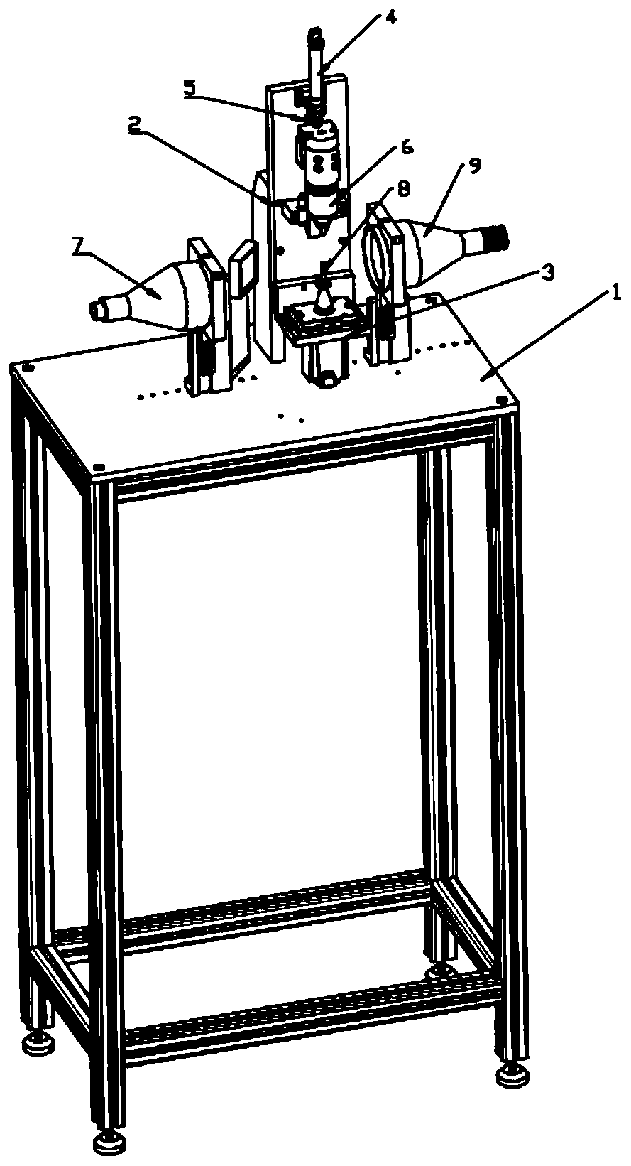
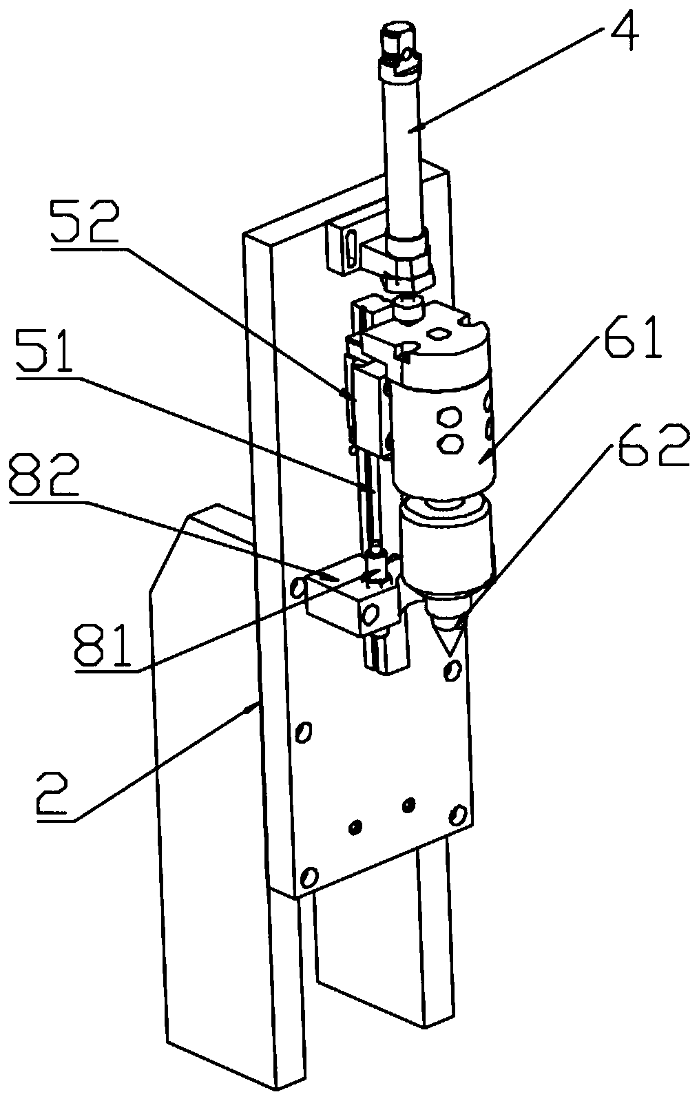
[0025] A crack detection device such as figure 2 As shown, it includes a worktable 1, a support 2, a rotary table 3, a first actuator 4, a guide mechanism 5, a pressing mechanism 6 and a camera 7, the support 2 and the rotary table 3 are arranged on the worktable 1, and the first An actuator 4 and guide mechanism 5 are arranged on the bracket 1, and the pressing mechanism 6 is arranged on the guide mechanism 5, and placed directly above the rotary table 3, the first actuator 4 can be a cylinder; the output end of the cylinder It is fixedly connected with the pressing mechanism 6, and drives the p...


PUM


Abstract

The invention discloses a crack detection device, which comprises a workbench, a bracket, a rotary machine table, a first actuator, a guide mechanism, a pressing mechanism and a camera. The support and the rotary machine table are arranged on the workbench. The first actuator and the guide mechanism are arranged on the bracket. The pressing mechanism is arranged on the guide mechanism and locatedright above the rotary machine table. The first actuator is used for driving the pressing mechanism to vertically move along the guide mechanism to fix a work piece placed on the rotary machine table.The camera is arranged on one side of the rotary machine table and used for collecting images of the work piece. The device is simple in structure and convenient to operate. Image acquisition is carried out by rotating the work piece 360 degrees, and crack detection on the surface of the work piece is thus achieved. Through active rotation of the rotary machine table and passive rotation of the pressing mechanism, the stability of the work piece during rotation is guaranteed. Through a conical pressing block and a cone-frustum-shaped base, the position of the work piece can be adjusted and fixed, and the work piece can rotate about the central axis thereof.

Description

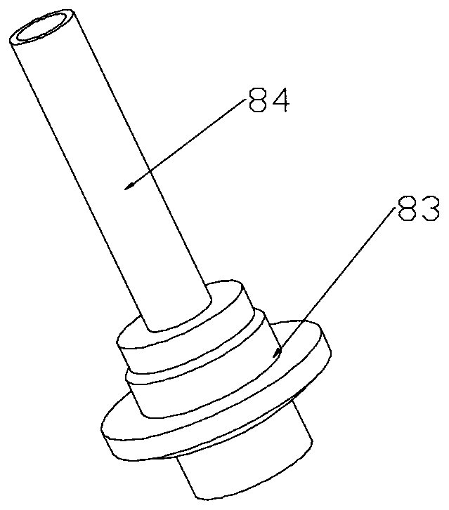
technical field [0001] The invention relates to the detection field, in particular to a crack detection device. Background technique [0002] Such as figure 1 as shown, figure 1 Shown is a schematic structural diagram of a fuel injector for a gasoline engine, the bottom 83 is in a stepped structure, and a tubular structure 84 extends upwards, and the inside is a through hole. And this workpiece is used in gasoline engine, has higher requirement to it, if crack appears on the surface, there will be certain potential safety hazard in use. Therefore, it is necessary to detect cracks on the surface. However, existing manufacturers usually use manual detection, that is, workers detect cracks on the surface of the workpiece through a microscope. It can be seen that a lot of manpower will be wasted through manual inspection, which will greatly increase production costs; and the accuracy rate is low, and false detections often occur; the most important thing is that workers use m...

Claims


Application Information

Patent Timeline
Patent Type & Authority Applications(China)
IPC IPC(8): G01N21/88G01N21/01
CPCG01N21/8851G01N21/01G01N2021/8887
Inventor 尤根·海瑞恩
Owner HAERING PRECISION TAICANG CO LTD
Learn More