Linear vortex brake device

An eddy current braking and linear technology, applied in the field of rail vehicle braking systems, can solve the problems of adding winding tooling, burning out coils, and magnetic pole shaking, etc., to reduce processing and production requirements, facilitate installation and maintenance, and facilitate installation and disassembly Effect

Inactive Publication Date: 2019-11-19
NANJING CRRC PUZHEN HAITAI BRAKE EQUIP CO LTD
View PDF8 Cites 0 Cited by
  • Summary
  • Abstract
  • Description
  • Claims
  • Application Information

AI Technical Summary

Problems solved by technology

If the current of the brake magnetic pole is forcibly increased on the original device, on the one hand, the coil may be burned out, causing the brake to fail. On the other hand, the increase of the braking force requires higher requirements on the strength of the force transmission parts, etc.
[0005] The existing fastening method of the magnetic pole is to cooperate with the groove of the yoke of the support beam assembly through two lifting lugs on the magnetic pole, and then fix it with fasteners such as screws. The design of the lifting lug has the following defects: On the one hand, it increases the processing difficulty of the pole, on the other hand, it increases the difficulty in the design of winding tooling and packaging tooling
The weight of the magnetic pole is about 24kg, and it is fixed by four screws and other fasteners, which is easy to cause the magnetic pole to shake, and the fastening strength is at risk
[0006] In addition, since the magnetic poles of the original device and the support beam are installed without error-proofing measures, there is a possibility that the magnetic poles may be installed reversely. If the installation is reversed, the eddy current braking force will drop sharply, seriously affecting driving safety.

Method used


Image

  • Linear vortex brake device
  • Linear vortex brake device
  • Linear vortex brake device

Examples


Embodiment Construction

[0026] In order to make the purpose, technical solutions and advantages of the embodiments of the present invention more clear, the technical solutions in the embodiments of the present invention will be clearly and completely described below in conjunction with the drawings in the embodiments of the present invention.

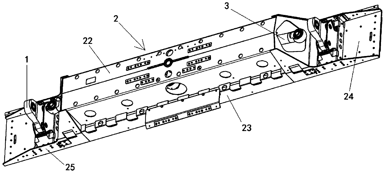
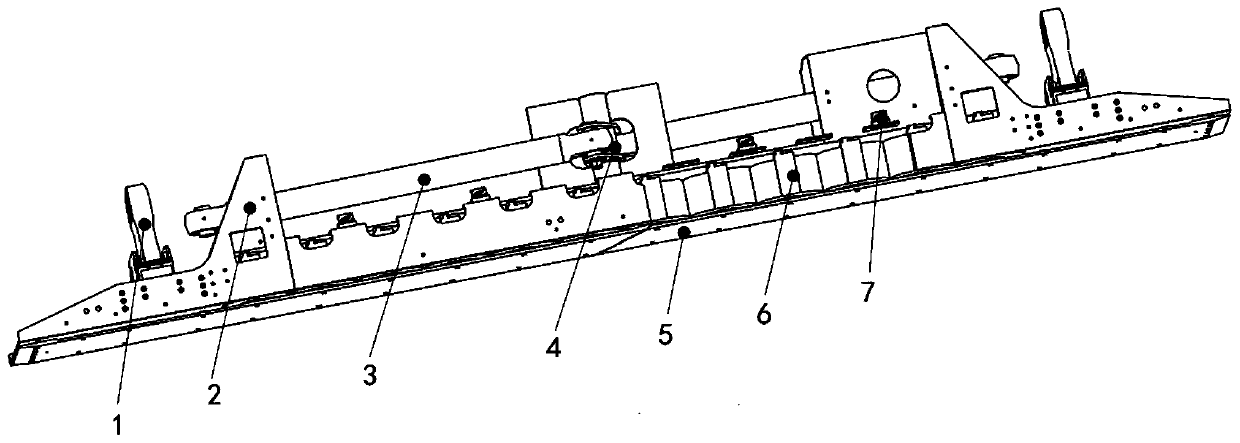
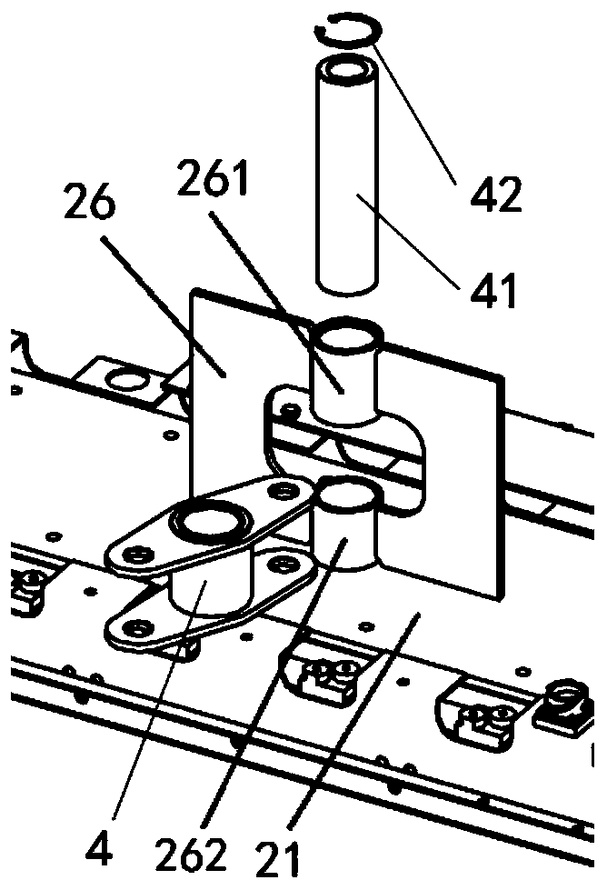
[0027] Such as Figure 1 to Figure 7 As shown, this embodiment is a linear eddy current braking device, including: a support beam assembly 2, two support arm assemblies 1, two pull rod assemblies 3, a lever assembly 4, several magnetic poles 6 and wear plates 5. The supporting arm assembly is connected with the support arm of the magnetic levitation vehicle to ensure the lateral displacement of the vehicle. The support beam component is the integrated main body of the device, which integrates other parts and is also an important part of transmitting torque; the lever component and the tie rod component cooperate to transmit the braking force to the vehicle; th...


PUM


Abstract

The invention relates to a linear vortex brake device comprising a supporting beam assembly, two supporting arm assemblies, two pull rod assemblies, a lever assembly and multiple magnetic poles. The magnetic poles are rigidly fixed to the bottom of the supporting beam assembly. The upper ends of the two supporting arm assemblies are connected with suspension frame support arms of a vehicle. The lower ends of the two supporting arm assemblies are fixed to the end portion of the supporting beam assembly. The lever assembly is arranged on the middle portion of the supporting beam assembly in a rotating manner. The inner ends of the two pull rod assemblies are hinged to the two ends of the lever assembly correspondingly. The outer ends of the two pull rod assemblies are connected with a suspension frame of the vehicle. According to the optimized fastening manner, the magnetic poles are fixed to the lower portions of magnet yokes of the supporting beam assembly through fastening bolts and lock washers, the manner is simple, installation and detachment of the magnetic poles are convenient, it is calculated that the fastening safety coefficient is far larger than 1.5, and safety and reliability are achieved. In addition, positioning pin holes are added to the magnetic poles and the magnet yokes, and on one hand, the structure optimization can be used for the reverse installation measure in the magnetic pole installation process.

Description

technical field [0001] The invention belongs to the technical field of rail vehicle braking systems, and in particular relates to a linear eddy current braking device suitable for maglev trains. Background technique [0002] Most existing maglev trains use linear eddy current braking devices for emergency braking. Linear eddy current braking technology uses the magnetic field generated by the braking magnetic pole under high-speed conditions to generate eddy currents on the side rails. According to Maxwell's law and Lenz's law, the magnetic field generated by the eddy current interacts with the original magnetic field to generate braking force. The braking force is finally transmitted to the vehicle bogie through the brake pole core, yoke, and tie rod assembly, so as to achieve braking. [0003] At present, the maximum speed of the Shanghai maglev train is 500km / h. The linear eddy current brake device used for emergency braking on the car continues to use the technical sche...

Claims


Application Information

Patent Timeline
Patent Type & Authority Applications(China)
IPC IPC(8): B60L7/28H02K49/04
CPCB60L7/28H02K49/04Y02T10/64
Inventor 刘京张东升杨俊刘寅虎刘元清牛瑞朱新宇曹云丽虞晓峰
Owner NANJING CRRC PUZHEN HAITAI BRAKE EQUIP CO LTD
Why Eureka
Try Eureka