


Quick Research
Generate reliable direction feasibility study reports for your R&D in just a few steps.

Technical Q&A
Discover and master advanced knowledge NOW. Basics, ideas, possibilities, all at once.

Find Solutions
As an expert in R&D theories, this can generate solutions to your technical problems instantly.

Evaluate Feasibility
Analyze your overall solution with one click, know your potential R&D risks in advance.

Monitor Landscape
Get weekly tech updates, stay abreast of the latest tech innovations and key insights.
Valve with an electromagnetic drive
An electromagnetic driver and driver technology, applied in the direction of electromagnets, electromagnets, circuits, etc. with armatures, can solve the problems of structural volume reduction, power reduction, etc., and achieve the effect of saving space
- Summary
- Abstract
- Description
- Claims
- Application Information
AI Technical Summary
Problems solved by technology
Method used
Image

Examples
Embodiment Construction
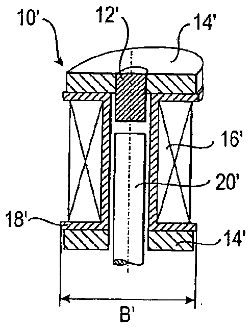
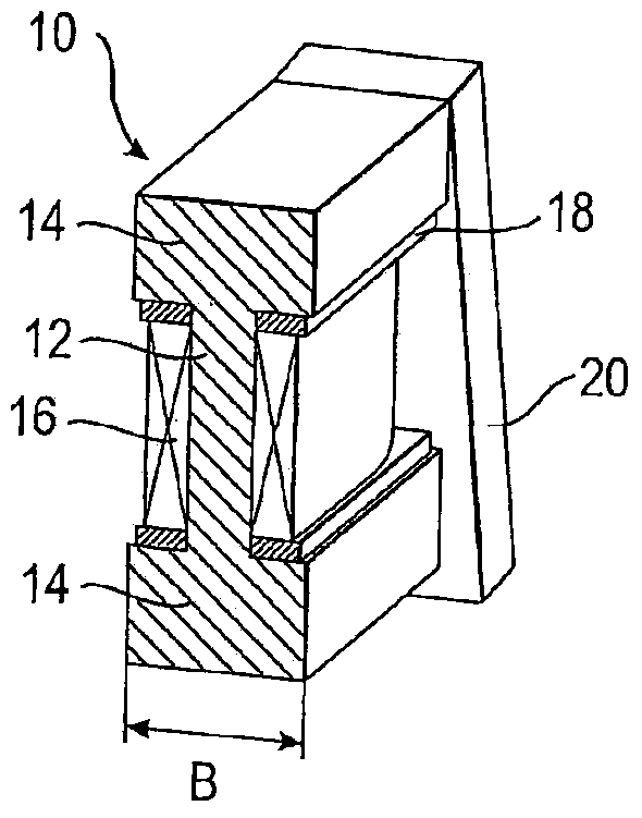
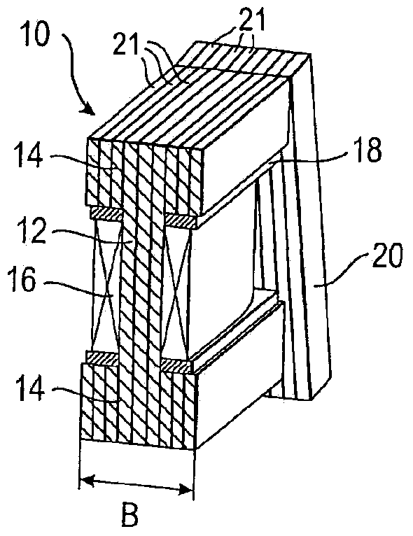
[0029] figure 2 A solenoid drive 10 is schematically shown for a valve according to the invention, more specifically a narrow valve with structural dimensions smaller than or equal to 5 mm, preferably approximately 4.5 mm. The driver 10 has a core 12 disposed between two poles 14 and formed in one piece therewith. The core 12 has disposed thereon a winding 16 formed of a plurality of copper turns (coils). There is also a coil former 18 arranged between the winding 16 and the pole 14, but this coil former differs from that of the prior art, at least in the direction of the dimension B which determines the structural dimensions of the valve, between the core 12 and the winding 16. There are no walls. The pole 14 protrudes over the winding 16 and cooperates with an armature 20 which is arranged relative to the pole 14 in such a way that it does not increase the structural size of the valve along the dimension B. and figure 2 Unlike the example shown, the coil carrier 18 can...
PUM
 Abstract
Description
Claims
Application Information
 - R&D Engineer
- R&D Manager
- IP Professional
- Industry Leading Data Capabilities
- Powerful AI technology
- Patent DNA Extraction
Browse by: Latest US Patents, China's latest patents, Technical Efficacy Thesaurus, Application Domain, Technology Topic, Popular Technical Reports.
© 2024 PatSnap. All rights reserved.Legal|Privacy policy|Modern Slavery Act Transparency Statement|Sitemap|About US| Contact US: help@patsnap.com