A magnetic fluid flywheel and its design method
A design method and magnetic fluid technology, applied in the field of satellite control, can solve the problems of high-speed rotor disturbance, long life difficulty, precision and complexity, etc., and achieve the effects of overcoming friction damping and wear, simple driving control circuit, and suppressing vibration and noise.
- Summary
- Abstract
- Description
- Claims
- Application Information
AI Technical Summary
Problems solved by technology
Method used
Image

Examples
Embodiment 1
[0060] A method for designing a magnetic fluid flywheel. An annular cavity is provided inside the magnetic fluid flywheel, and a conductive fluid is filled in the annular cavity; a magnetic steel is provided on the axial side of the annular cavity, and the circumference of the annular cavity Electrodes are provided on both the inner side and the outer side; the conductive fluid rotates under the action of the potential difference and the magnetic field;
[0061] The MHD flywheel design includes the following steps:
[0062] S1. Based on the externally set angular momentum H, set the fluid angular velocity ω FL ;
[0063] S2, according to H=Jω FL Calculate the fluid mass moment of inertia J; then select the conductive fluid material and determine the fluid density ρ of the conductive fluid material; then according to J=Ahρr 2 , to determine N sets of parameter combinations, each set of parameter combinations includes the outer ring radius r 0 , inner ring radius r i and ch...
Embodiment 2
[0075] A method for designing a magnetic fluid flywheel. An annular cavity is provided inside the magnetic fluid flywheel, and a conductive fluid is filled in the annular cavity; a magnetic steel is provided on the axial side of the annular cavity, and the circumference of the annular cavity Electrodes are provided on both the inner side and the outer side; the conductive fluid rotates under the action of the potential difference and the magnetic field;
[0076] The MHD flywheel design includes the following steps:
[0077] S10. Based on the externally set angular momentum H, set the fluid angular velocity ω FL ;
[0078] S20, according to H=Jω FL Calculate the fluid mass moment of inertia J; then select the conductive fluid material and determine the fluid density ρ of the conductive fluid material; then according to J=Ahρr 2 , to determine N sets of parameter combinations, each set of parameter combinations includes the outer ring radius r 0 , inner ring radius r i and ...
Embodiment 3
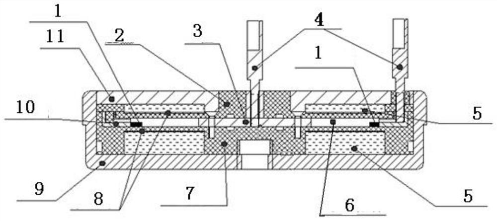
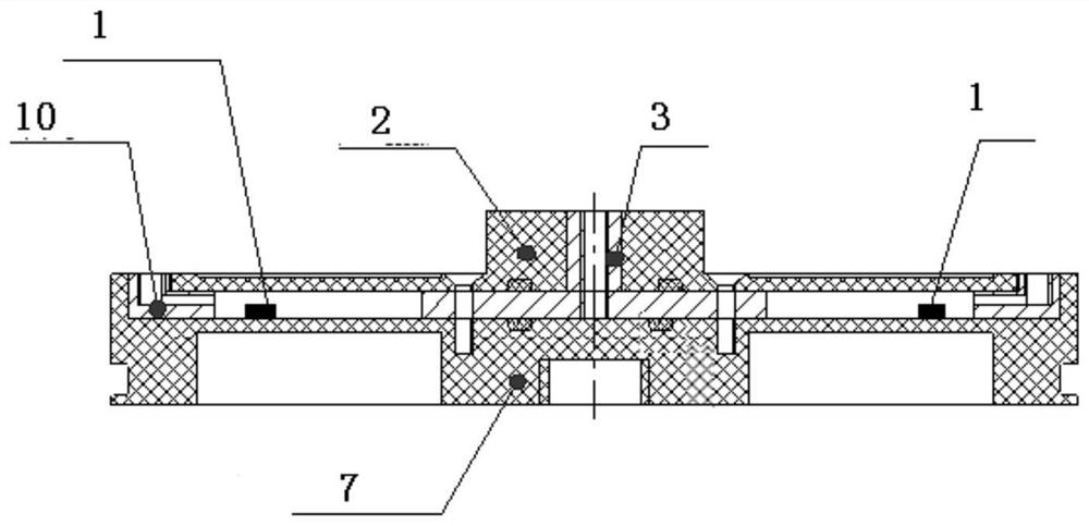
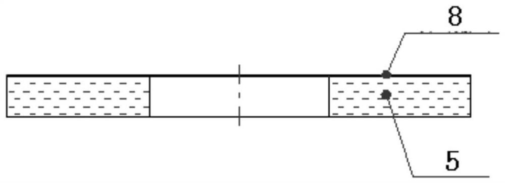
[0089] A magnetic fluid flywheel, comprising a flywheel body, a speed measuring device, and a flywheel circuit; the flywheel body includes a conductive fluid ring assembly, a magnetic steel assembly, and electrodes, such as figure 1 shown;
[0090] The magnetic steel component can generate a magnetic field to act on the conductive fluid in the conductive fluid ring component; when the conductive fluid in the conductive fluid ring component rotates, it can generate output torque and angular momentum; the electrodes are used to give the conductive fluid energizing a conductive fluid within the fluid ring assembly, said conductive fluid rotating under the action of a potential difference and a magnetic field;
[0091] The speed measuring device is used to measure the fluid angular velocity of the conductive fluid, and then send it to the flywheel circuit. The speed measuring device adopts a piezoelectric sensor; Momentum, which controls the energization voltage of the electrodes...
PUM
 Abstract
Description
Claims
Application Information
 - R&D
- Intellectual Property
- Life Sciences
- Materials
- Tech Scout
- Unparalleled Data Quality
- Higher Quality Content
- 60% Fewer Hallucinations
Browse by: Latest US Patents, China's latest patents, Technical Efficacy Thesaurus, Application Domain, Technology Topic, Popular Technical Reports.
© 2025 PatSnap. All rights reserved.Legal|Privacy policy|Modern Slavery Act Transparency Statement|Sitemap|About US| Contact US: help@patsnap.com