
Differential contact module, differential connector and differential pair shielding structure

A technology of shielding structure and contact module, applied in the direction of connection, connecting device parts, electrical components, etc., can solve the problem that the differential contact module cannot solve the electromagnetic interference of the differential pair, so as to reduce the leakage of magnetic field energy, and the structure is simple and convenient. The effect of assembly

Active Publication Date: 2019-11-15
CHINA AVIATION OPTICAL-ELECTRICAL TECH CO LTD
View PDF17 Cites 10 Cited by
  • Summary
  • Abstract
  • Description
  • Claims
  • Application Information

AI Technical Summary

Problems solved by technology

[0004] The purpose of the present invention is to provide a differential contact module to solve the problem that the differential contact module in the prior art cannot solve the electromagnetic interference between differential pairs; the purpose of the present invention is also to provide a differential contact module using the differential contact module. connector; the object of the present invention is also to provide a differential pair shielding structure of the differential contact module

Method used


Image

  • Differential contact module, differential connector and differential pair shielding structure
  • Differential contact module, differential connector and differential pair shielding structure
  • Differential contact module, differential connector and differential pair shielding structure

Examples


Embodiment 2

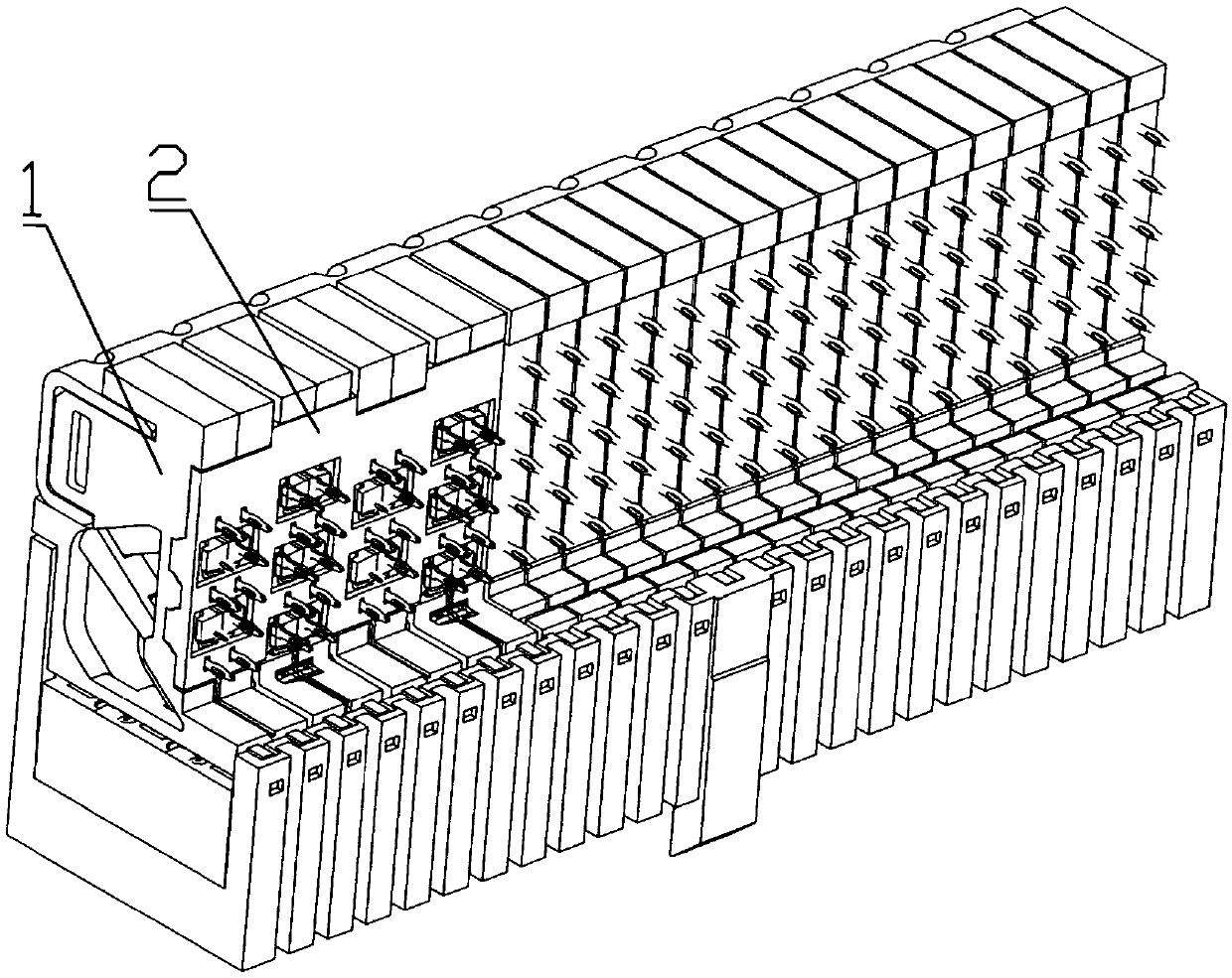
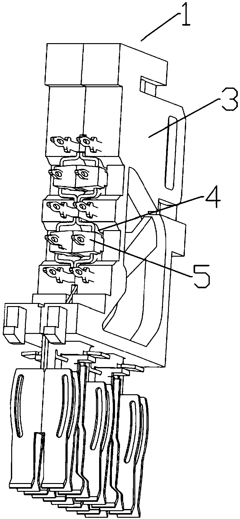
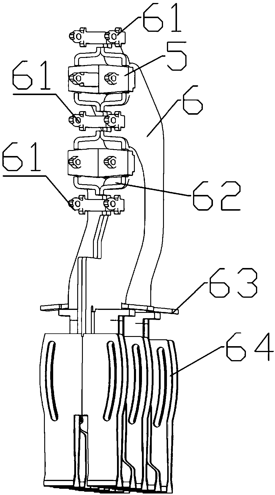
[0052] Embodiment 2 of the differential connector of the present invention. In this embodiment, the structure of the differential connector is simplified. Specifically, the differential connector includes a housing and a differential contact module arranged in the housing. The differential contact module includes The insulator and the differential signal pair, the insulator is fixed with two relatively fitted shielding sheets, and the opposite sides of the two shielding sheets are provided with accommodating grooves for accommodating the differential signal pair, and the corresponding accommodating grooves on the two shielding sheets are snapped together Accommodating holes for accommodating the differential signal pairs are formed to fully surround and shield the differential signal pairs.

[0053] By arranging two shielding sheets and fitting them together, and at the same time providing accommodation grooves extending backwards on the fitting surfaces, the corresponding two ...


PUM


Abstract

The invention relates to a differential contact module, a differential connector and a differential pair shielding structure. The differential pair shielding structure comprises two oppositely-bondedshielding sheets. The opposite sides of two shielding sheets are provided with accommodation slots for accommodating a differential signal pair. The corresponding accommodation slots on two shieldingsheets are buckled and assembled to form an accommodation hole for accommodating the differential signal pair to fully surround and shield the differential signal pair. The differential signal pair isintegrally located in the accommodation hole from a socket end to a plug end, and fully surrounded and shielded by two shielding sheets to ensure that any two adjacent differential pairs are completely isolated by the shielding sheets. An electromagnetic field between two signal conductors is effectively restrained. The leakage of magnetic field energy is reduced. Signal interference is reduced.The structure is relatively simple. At the same time, two shielding sheets are oppositely bonded, which is convenient for assembly and processing.

Description

technical field [0001] The invention relates to a differential contact module, a differential connector, and a differential pair shielding structure. Background technique [0002] Differential connectors are mainly used in occasions that require high-speed, high-quality transmission signals. Its main components include a housing and a differential contact module disposed in the housing. The differential contact module includes an insulator and a contact that is fixedly assembled on the insulator. The contacts include differential signal pairs and grounding shields. A differential connector often includes multiple differential contact modules. The differential contact modules are fixedly arranged side by side in corresponding slots of the shell layer by layer to realize the integration of each differential contact module. [0003] In the current differential connector, in order to reduce the electromagnetic interference between the differential pair signals of different diffe...

Claims


Application Information

Patent Timeline
IPC IPC(8): H01R13/6586H01R13/514
CPCH01R13/514H01R13/6586
Inventor 袁俊峰
Owner CHINA AVIATION OPTICAL-ELECTRICAL TECH CO LTD
Learn More