
Pulverized solid fuel nozzle tip

A technology of solid fuel and nozzle head, which is applied in the direction of gas fuel burner, combustion using block fuel and liquid fuel, burner burning powder fuel, etc., and can solve problems such as reverse flow

Inactive Publication Date: 2003-04-02
GENERAL ELECTRIC TECH GMBH
View PDF8 Cites 1 Cited by
  • Summary
  • Abstract
  • Description
  • Claims
  • Application Information

AI Technical Summary

Problems solved by technology

On the other hand, if the flow velocity in the fuel-air shroud is allowed to drop significantly due to the nozzle tip bypass, it is possible to create a low pressure / velocity zone in the fuel-air shroud, causing reverse flow and particle deposition in this annulus

Method used

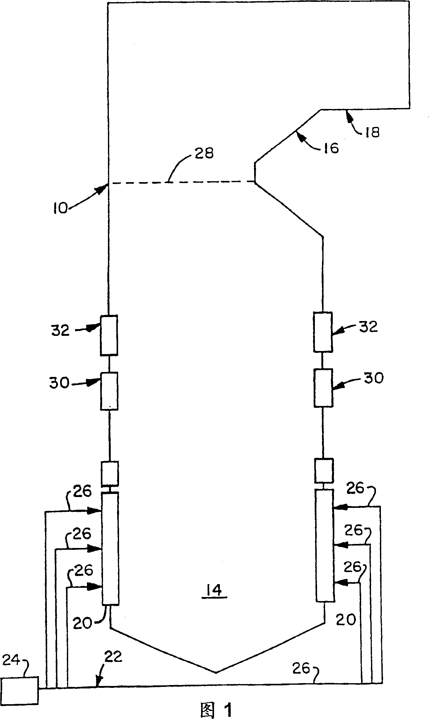

Image

  • Pulverized solid fuel nozzle tip
  • Pulverized solid fuel nozzle tip
  • Pulverized solid fuel nozzle tip

Examples


no. 1 approach

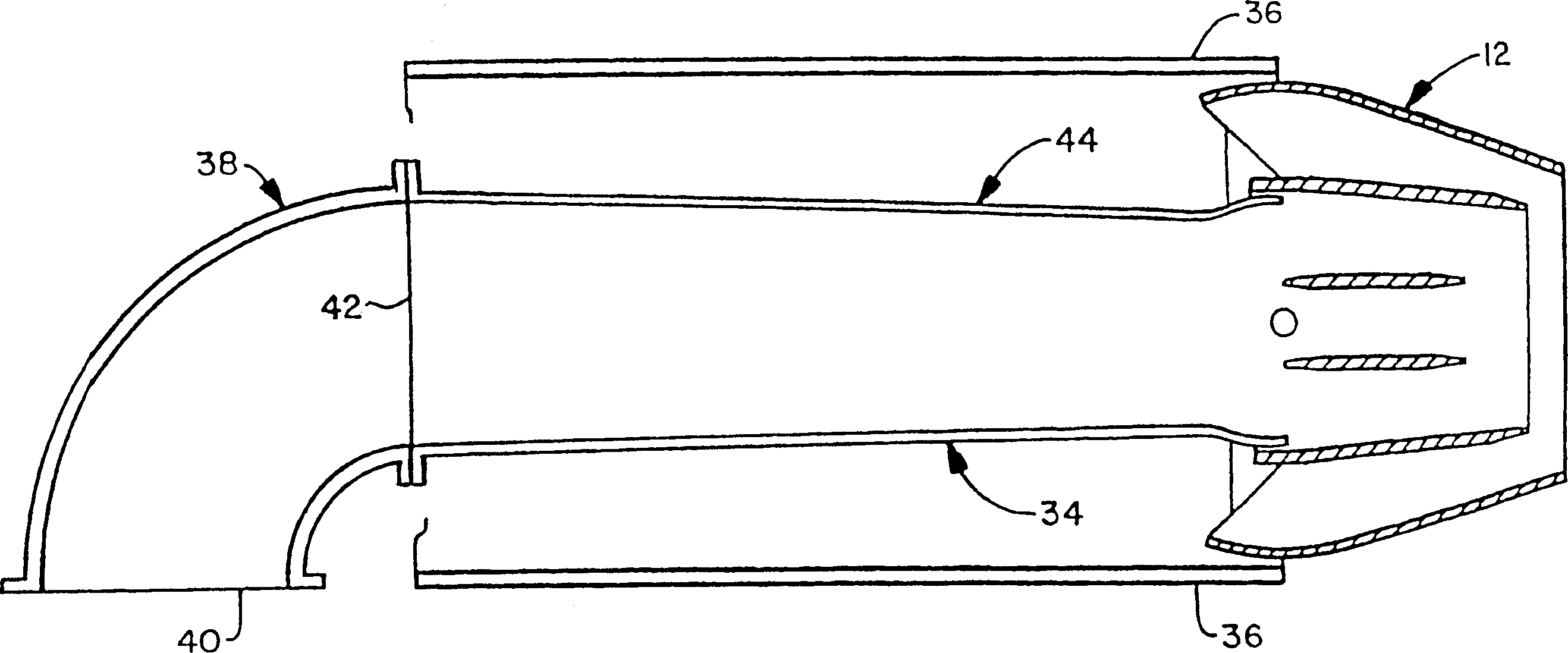
[0042] The pulverized solid fuel nozzle 34 may be mounted in the fuel chamber 36 using any conventional form of mounting means suitable for such purpose. Reference attached figure 2 It will be well understood that the pulverized solid fuel nozzle 34 is included in figure 2 The elbow portion generally indicated by reference numeral 38 in the figure 2 Not described in, the elbow is designed at one end of the figure 2 Indicated by reference numeral 40, it is connected with the pulverized solid fuel delivery pipe 26. The other end of rib-shaped portion 38 is represented by numeral 42, with reference to figure 2 It can be seen that by applying any conventional form of fastening means suitable for such purpose, the attachment to figure 2 On the longitudinally extending portion indicated generally by reference numeral 44. The length of the longitudinally extending portion 44 is such that it substantially corresponds to the depth of the fuel chamber 36 . The pulverized solid fue...


PUM


Abstract

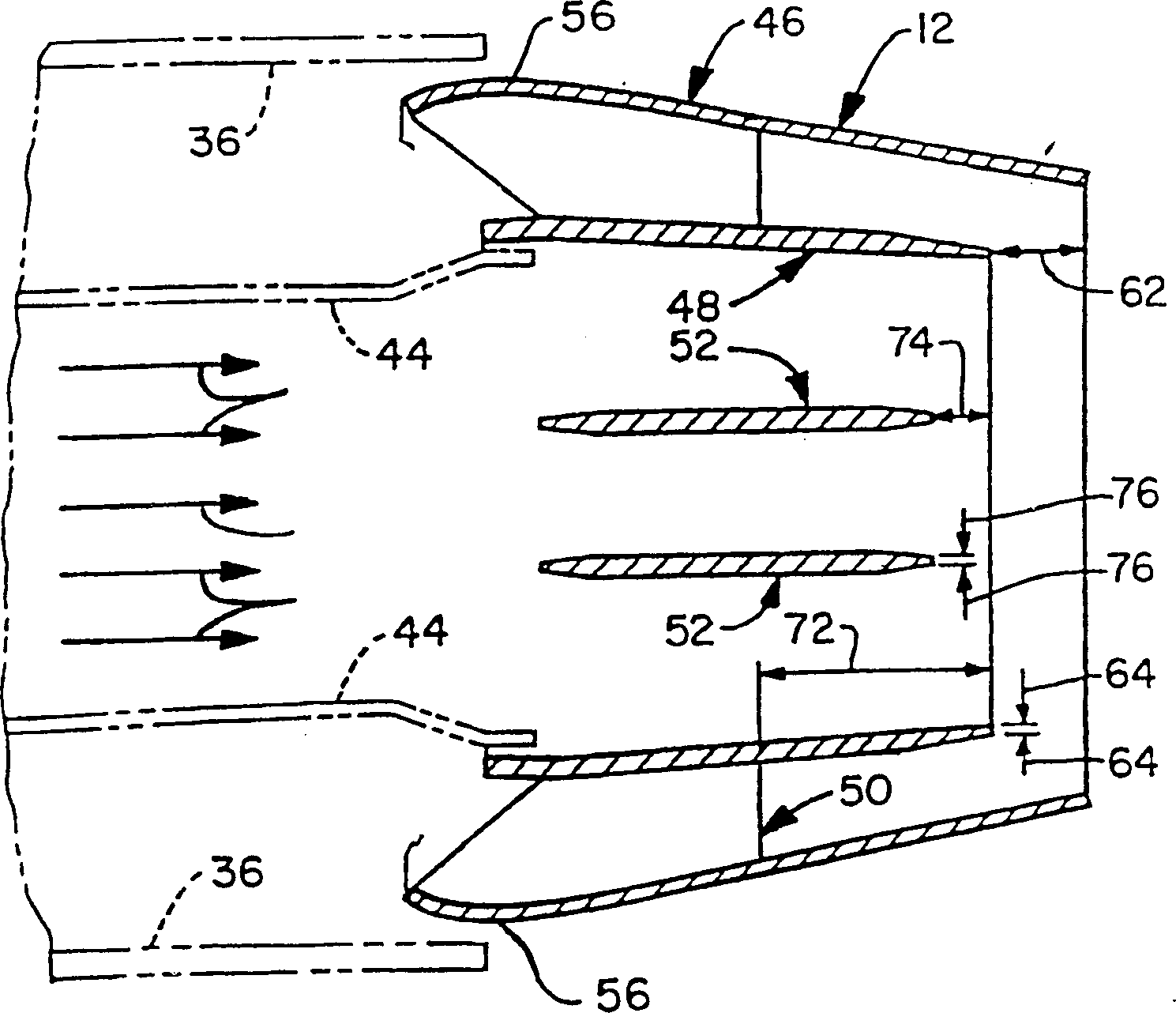
A minimum recirculation flame control (MRFC) solid fuel nozzle tip (12) that is particularly suited to being cooperatively associated with a pulverized solid fuel nozzle (34) of a firing system of the type employed in a pulverized solid fuel-fired furnace (10). The MRFC solid fuel nozzle tip (12) when so employed is operative to minimize low and negative, i.e., recirculation, velocity regions of the exit plane of the MRFC solid fuel nozzle tip (12), and to reduce available deposition surface on the MRFC solid fuel nozzle tip (12), and to vary the nozzle tip (12) / solid fuel nozzle (34) thermal conditions to keep the 'hot' solid fuel particulate matter from depositing on available metal platework surface of the MRRC solid fuel nozzle tip (12). The MRFC solid fuel nozzle tip (12) includes fuel air shroud means (46), primary air shroud means (48) located within the fuel air shroud means (46), fuel air shroud support means (50) operative for supporting the primary air shroud means (48) relative to the fuel air shroud means (46), and splitter plate means (52) mounted in supported relation within the primary air shroud means (48).

Description

technical field [0001] The present invention relates to combustion systems for use in pulverized solid fuel combustion furnaces, and in particular to minimum recirculation flame control (MRFC) solid fuel nozzle tips for use in such combustion systems. Background technique [0002] The use of pulverized solid fuel nozzle tips in combustion systems of the type used in pulverized solid fuel fired furnaces has long been known in the prior art. By way of example, and not limitation, reference is made to U.S. Patent No. 2,895,435, issued July 21, 1959, entitled "Inclined Nozzle for Fuel Burners," and assigned to the same applicant as the present patent the assignee. According to US Patent No. 2,895,435, there are angled nozzles which are said to produce a substantially uniform distribution of the fuel-air mixture exiting the angled nozzles and a substantially uniform velocity across the discharge openings of the angled nozzles into the furnace. Therefore, the inclined nozzle com...

Claims


Application Information

Patent Timeline
Patent Type & Authority Patents(China)
IPC IPC(8): F23C5/06F23C7/02F23D1/00
CPCF23C7/02F23C5/06F23D2201/101F23D1/00
Inventor T·G·杜拜M·A·方T·D·赫尔勒维尔C·Q·梅尼S·斯里尼瓦萨查尔M·A·托坎
Owner GENERAL ELECTRIC TECH GMBH
Learn More